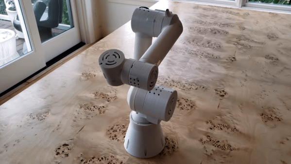
[Dan Royer] is taking some inspiration from Prusa’s business and is trying to build the same sort of enterprise around open source 3D printable robot arms. His 6 axis robot arm is certainly a strong first step on that road.
As many people have learned, DIY robot arms are pretty difficult. [Dan]’s arm has the additional complexity of being 3D printable with the ambitious goal of managing a 2kg payload at 840mm of reach. He’s already made significant progress. There’s a firmware, set of custom electronics, and a Fusion 360 project anyone can download and checkout. You can even control it with an Xbox controller.
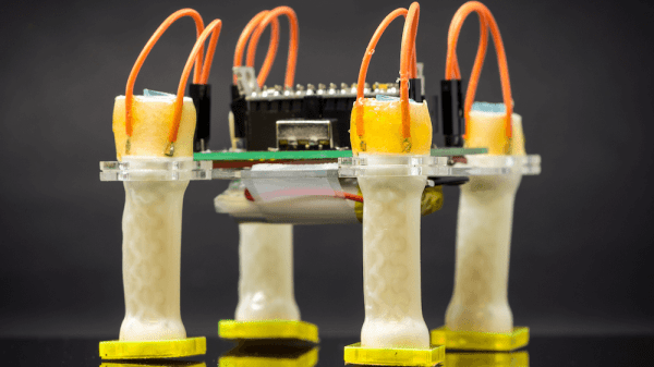
The main board is an Arduino shield which outputs step and direction signals to stepper drivers. The gears are cycloidal and it appears there’s even some custom machining going on. When the parts are all laid out it becomes clear just how much effort has been put into this design.
It should be a pretty nice robot and might finally spur some of us to build the Iron Man style robot assistants we’ve always wanted. You can see the robot in action after the break.
Continue reading “Sixi 2, An Open Source 3D Printable 6 Axis Robot Arm”