Designing For Fab: A Heads-Up Before Designing PCBs For Professional Assembly

Designing pcbs for assembly is easy, right? We just squirt all the footprints onto a board layout, connect all the traces, send out the gerbers and position files, and we’re done–right?

Whoa, hold the phone, there, young rogue! Just like we can hack together some working source code with variables named after our best friends, we can also design our PCBs in ways that make it fairly difficult to assemble.

However, by following the agreed-upon design specs, we’ll put ourselves on track for success with automated assembly. If we want another party to put components on our boards, we need to clearly communicate the needed steps to get there. The best way to do so is by following the standards.

Proper Footprint Orientation
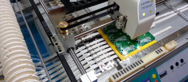
Now, for a momImage Credit: https://encrypted-tbn2.gstatic.com/images?q=tbn:ANd9GcQBEztpnSxpN_IRjq3y8GbetrMHKuoSu_s6myiFOHilL2FlQKyLrgent, let’s imagine ourselves as the tip of a vacuum pickup tool on a pick-and-place machine. These tools are designed to pick up components on the reel from their centroid and plunk them on their corresponding land pattern. Seems pretty straightforward, right? It is, provided that we design our footprints knowing that they’ll one day come face-to-face with the pick-and-place machine.

To get from the reel to the board, we, the designers, need two bits of information from out part’s datasheet: the part centroid and the reel orientation.

The part centroid is an X-Y location that calls out the center-of-mass of the part. It basically tells the machine: “pick me up from here!” As designers, it’s our responsibility to design all of our footprints such that the footprint origin is set at the part’s centroid. If we forget to do so, the pick-and-place will try to suck up our parts from a location that may not stick very well to the package, such as: the corner.

Continue reading “Designing For Fab: A Heads-Up Before Designing PCBs For Professional Assembly”

How A Hacker Remembers A PIN

If you have more than a few bank cards, door-entry keycodes, or other small numeric passwords to remember, it eventually gets to be a hassle. The worst, for me, is a bank card for a business account that I use once in a blue moon. I probably used it eight times in five years, and then they gave me a new card with a new PIN. Sigh.

Quick, What’s My PIN?

How would a normal person cope with a proliferation of PINs? They’d write down the numbers on a piece of paper and keep it in their wallet. We all know how that ends, right? A lost wallet and multiple empty bank accounts. How would a hacker handle it? Write each number down on the card itself, but encrypted, naturally, with the only unbreakable encryption scheme there is out there: the one-time pad (OTP).

The OTP is an odd duck among encryption methods. They’re meant to be decrypted in your head, but as long as the secret key remains safe, they’re rock solid. If you’ve ever tried to code up the s-boxes and all that adding, shifting, and mixing that goes on with a normal encryption method, OTPs are refreshingly simple. The tradeoff is a “long” key, but an OTP is absolutely perfect for encrypting your PINs.

The first part of this article appears to be the friendly “life-hack” pablum that you’ll get elsewhere, but don’t despair, it’s also a back-door introduction to the OTP. The second half dives into the one-time pad with some deep crypto intuition, some friendly math, and hopefully a convincing argument that writing down your encrypted PINs is the right thing to do. Along the way, I list the three things you can do wrong when implementing an OTP. (And none of them will shock you!) But in the end, my PIN encryption solution will break one of the three, and remain nonetheless sound. Curious yet? Read on.

Continue reading “How A Hacker Remembers A PIN”

OBDII to Speed Pulse: Atmel ICE

Building An OBD Speed Pulse: Behold The ICE

I am a crappy software coder when it comes down to it. I didn’t pay attention when everything went object oriented and my roots were always assembly language and Real Time Operating Systems (RTOS) anyways.

So it only natural that I would reach for a true In-Circuit-Emulator (ICE) to finish of my little OBDII bus to speed pulse generator widget. ICE is a hardware device used to debug embedded systems. It communicates with the microcontroller on your board, allowing you to view what is going on by pausing execution and inspecting or changing values in the hardware registers. If you want to be great at embedded development you need to be great at using in-circuit emulation.

Not only do I get to watch my mistakes in near real time, I get to make a video about it.

Getting Data Out of a Vehicle

I’ve been working on a small board which will plug into my car and give direct access to speed reported on the Controller Area Network (CAN bus).

To back up a bit, my last video post was about my inane desire to make a small assembly that could plug into the OBDII port on my truck and create a series of pulses representing the speed of the vehicle for my GPS to function much more accurately. While there was a wire buried deep in the multiple bundles of wires connected to the vehicle’s Engine Control Module, I have decided for numerous reasons to create my own signal source.

At the heart of my project is the need to convert the OBDII port and the underlying CAN protocol to a simple variable representing the speed, and to then covert that value to a pulse stream where the frequency varied based on speed. The OBDII/CAN Protocol is handled by the STN1110 chip and converted to ASCII, and I am using an ATmega328 like found on a multitude of Arduino’ish boards for the ASCII to pulse conversion. I’m using hardware interrupts to control the signal output for rock-solid, jitter-free timing.

Walk through the process of using an In-Circuit Emulator in the video below, and join me after the break for a few more details on the process.

Continue reading “Building An OBD Speed Pulse: Behold The ICE”

The Dangers Of Engineering While Unlicensed

Citizen engineers, beware the Beaver State. If you want to discuss engineering in a public setting, you’d better have a license. If you don’t, you could end up like Oregon resident Mats Järlström — paying a $500 fine and being threatened with even larger civil penalties and jail time.

The story of how Järlström became ensnared in this unfortunate series of events begins innocently enough, and it’s a story that any Hackaday reader can probably relate to. After his wife received a traffic ticket in the mail from a red-light camera in the town of Beaverton, Järlström began pondering the math of traffic signal timing. After a little digging, he found the formula used for calculating the time traffic signals stay in the yellow stage. Moreover, he found a flaw in the formula, which dates back to 1959, that could lead to incorrect violations issued by automated traffic cameras.

Continue reading “The Dangers Of Engineering While Unlicensed”

These Twenty Designs Just Won $1000 In The Hackaday Prize

Today we’re excited to announce the winners of the Design Your Concept phase of The Hackaday Prize. These projects just won $1000 USD, and will move on to the final round this fall.

Hackaday is currently hosting the greatest hardware competition on Earth. We’re giving away thousands of dollars to hardware creators to build the next great thing. Last week, we wrapped up the first of five challenges. It was all about showing a design to Build Something That Matters. Hundreds entered and began their quest to build a device to change the world.

There are still four more challenges to explore over the next few months. So far the results have been spectacular. But we’re only a fifth of the way through the Hackaday Prize. So as you celebrate and congratulate the twenty projects below, there’s ample opportunity to get in the game with your own project.

The winners for the Design Your Concept portion of the Hackaday Prize are, in no particular order:

Design Your Concept Hackaday Prize Finalists:

Continue reading “These Twenty Designs Just Won $1000 In The Hackaday Prize”

A Queen Mystery: The Legend Of The Deacy Amp

It sounds like a scene from a movie. A dark night in London, 1972. A young man walks alone, heading home after a long night of practicing with his band. His heavy Fender bass slung over his back, he’s weary but excited about the future. As he passes a skip (dumpster for the Americans out there), a splash of color catches his attention. Wires – not building power wires, but thinner gauge electronics connection wire. A tinkerer studying for his Electrical Engineering degree, the man had to investigate. What he found would become rock and roll history, and the seed of mystery stretching over 40 years.

The man was John Deacon, and he had recently signed on as bassist for a band named Queen. Reaching into the skip, he found the wires attached to a circuit board. The circuit looked to be an amplifier. Probably from a transistor radio or a tape player. Queen hadn’t made it big yet, so all the members were struggling to get by in London.

Deacon took the board back home and examined it closer. It looked like it would make a good practice amplifier for his guitar. He fit the amp inside an old bookshelf speaker, added a ¼ “ jack for input, and closed up the case. A volume control potentiometer dangled out the back of the case. Power came from a 9-volt battery outside the amp case. No, not a tiny transistor battery; this was a rather beefy PP-9 pack, commonly used in radios back then. The amp sounded best cranked all the way up, so eventually, even the volume control was removed. John liked the knobless simplicity – just plug in the guitar and play. No controls to fiddle with.

And just like that, The Deacy amp was born.

Continue reading “A Queen Mystery: The Legend Of The Deacy Amp”

Using Modern C++ Techniques With Arduino

C++ has been quickly modernizing itself over the last few years. Starting with the introduction of C++11, the language has made a huge step forward and things have changed under the hood. To the average Arduino user, some of this is irrelevant, maybe most of it, but the language still gives us some nice features that we can take advantage of as we program our microcontrollers.

Modern C++ allows us to write cleaner, more concise code, and make the code we write more reusable. The following are some techniques using new features of C++ that don’t add memory overhead, reduce speed, or increase size because they’re all handled by the compiler. Using these features of the language you no longer have to worry about specifying a 16-bit variable, calling the wrong function with NULL, or peppering your constructors with initializations. The old ways are still available and you can still use them, but at the very least, after reading this you’ll be more aware of the newer features as we start to see them roll out in Arduino code.
Continue reading “Using Modern C++ Techniques With Arduino”