PiSound, The Audio Card For The Raspberry Pi

Kids today are being loud with their ‘drum machines’ and ‘EDM’. Throw some Raspberry Pis at them, and there’s a need for a low-latency sound card with MIDI and all the other accouterments of the modern, Skrillex-haired rocker. That’s where PiSound comes in.

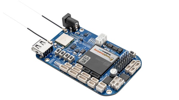
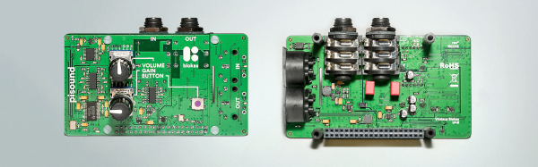
Of course, the Pi already comes with audio out, but that’s not enough if you want to do some real audio processing. You need audio in as well, and while you’re messing around with that, adding some high-quality opamps, ADCs, DACs, and some MIDI would be a good idea. This is what the PiSound is all about.

[Pranciskus], the guy who has been working on the PiSound for a while now, developed this multitool for audio on a tiny Linux system. One of the killer features on the PiSound is ‘The Button’, a simple tact switch that runs a script if the button is pressed, another script if the button is held down, and two more if the button is pressed two or three times. This is actually a pretty nifty UI, and we wouldn’t mind seeing this on a few more Pi accessories.

If you’d like to see some example projects using the PiSound, there example MIDI controllers, networked audio players, and some goofing around with LV2 plugins over here.

Retrotechtacular: How Old Is The Remote?

A few weeks ago we covered a (probably) bogus post about controlling a TV with the IR from a flame. That got us thinking about what the real origin of the remote control was. We knew a story about the 38 kHz frequency commonly used to modulate the IR. We’ve heard that it was from sonar crystals used in earlier sonic versions of remotes. Was that true? Or just an urban myth? We set out to find out.

Surprise! Remotes are Old!

If you are a younger reader, you might assume TVs have always had remotes. But for many of us, remotes seem like a new invention. If you grew up in the middle part of the last century it is a good bet you were your dad’s idea of a remote control: “Get up and turn the channel!” Turns out remotes have been around for a long time, though. They just weren’t common for a long time.

If you really want to stretch back, [Oliver Lodge] used a radio to move a beam of light in 1894. In 1896, [Marconi] and some others made a bell ring by remote control. [Tesla] famously showed a radio-controlled boat in 1898. But none of these were really remote controls like we think of for a television.

mysteryOf course, TV wouldn’t be around for a while, but by the 1930’s many radio manufacturers had wired remotes for radios. People didn’t like the wires, so Philco introduced the Mystery Control in 1939. This used digital pulse coding and a radio transmitter. That’s a fancy way of saying it had a dial like an old telephone. As far as we can tell, this was the first wireless remote for a piece of consumer equipment.

Continue reading “Retrotechtacular: How Old Is The Remote?”

Super Computing With Mini ITX Cluster

[Colin Alston] was able to snag a handful of Mini ITX motherboards for cheap and built a mini super computer he calls TinyJaguar. Named partly after the AMD Sempron 2650 APU, the TinyJaguar boasts four, yes that’s four MSI AM1I Mini-ITX motherboards, each with 4GB of DDR memory.

A Raspberry Pi with custom software manages the cluster, and along with some TTL and relays, controls the power to the four nodes. The mini super computer resides in a custom acrylic case held together by an array of 3D printed parts and fasteners.There’s even a rack-like faceplate near the bottom to host the RPi, an Ethernet switch, an array of status LEDs, and the two buttons.

With 16 total cores of computing power (including GPU), the TinyJaguar is quite capable of doing some pretty cool stuff such as running Jupyter notebook with IPyParallel. [Colin] ran into some issues getting the GPU to behave with PyOpenCL. It took a bit of pain and time, but in the end he was able to get the GPUs up, and wrote a small message passing program to show two of the cores were up and working together.

Be sure to check out [Colin’s] super computer project page, specifically the ten project logs that walk through everything that went into this build. He also posted his code if you want to take a look under the hood.

Scrap Wood And Metal Combined For DIY Mecanum Wheels

Some scrap wood, a few pieces of sheet metal, a quartet of old gear motors, and a few basic hand tools. That’s all it takes to build an omni-bot with Mecanum wheels, if you’ve got a little know-how too.

For the uninitiated, Mecanum wheels can rotate in any direction thanks to a series of tapered rollers around the circumference that are canted 45° relative to the main axle.  [Navin Khambhala]’s approach to Mecanum wheel construction is decidedly low tech and very labor intensive, but results in working wheels and a pretty agile bot. The supports for the rollers are cut from sheet steel and bent manually to hold the wooden rollers, each cut with a hole saw and tapered to a barrel shape on a makeshift lathe. Each wheel is connected directly to a gear motor shaft, and everything is mounted to a sheet steel chassis. The controls are as rudimentary as the construction methods, but the video below shows what a Mecanum-wheeled bot can do.

There’s a lot of room here for improvement, but mainly in the manufacturing methods. The entire wheel could be 3D printed, for instance, or even laser cut from MDF with a few design changes. But [Navin] scores a win for making a working wheel and a working bot from almost nothing.

Continue reading “Scrap Wood And Metal Combined For DIY Mecanum Wheels”

The BeagleBone Blue – Perfect For Robots

There’s a new BeagleBone on the block, and it’s Blue. The BeagleBone Blue is built for robots, and it’s available right now.

If a cerulean BeagleBone sounds familiar, you’re not wrong. About a year ago, the BeagleBone Blue was introduced in partnership with UCSD. This board was meant for robotics, and had the peripherals to match. Support for battery charging was included, as well as motor drivers, sensor inputs, and wireless. If you want to put Linux on a moving thingy, there are worse choices.

The newly introduced BeagleBone Blue is more or less the same. A 9-axis IMU, barometer, motor driver, quad encoder sensor, servo driver, and a balancing LiPo charger are all included. The difference in this revision is the processor. That big square of epoxy in the middle of the board is the Octavo Systems OSD3358, better known as a BeagleBone on a chip. This is the first actual product we’ve seen using this neat chip, but assuredly not the last – a few people are working on stuffing this chip onto a board that fits in mini Altoids tins.

How An Oscilloscope Probe Works, And Other Stories

The oscilloscope is probably the most versatile piece of test equipment you can have on your electronics bench, offering a multitude of possibilities for measuring timing, frequency and voltage as well as subtleties in your circuits revealed by the shape of the waveforms they produce.

On the front of a modern ‘scope is a BNC socket, into which you can feed your signal to be investigated. If however you simply hook up a co-axial BNC lead between source and ‘scope, you’ll immediately notice some problems. Your waveforms will be distorted. In the simplest terms your square waves will no longer be square.

Why is this? Crucial to the operation of an oscilloscope is a very high input impedance, to minimise current draw on the circuit it is investigating. Thus the first thing that you will find behind that BNC socket is a 1 megohm resistor to ground, or at least if not a physical resistor then other circuitry that presents its equivalent. This high resistance does its job of presenting a high impedance to the outside world, but comes with a penalty. Because of its high value, the effects of even a small external capacitance can be enough to create a surprisingly effective low or high pass filter, which in turn can distort the waveform you expect on the screen.

The answer to this problem is to be found in your oscilloscope probe. It might seem that the probe is simply a plug with a bit of wire to a rigid point with an earth clip, but in reality it contains a simple yet clever mitigation of the capacitance problem.

Continue reading “How An Oscilloscope Probe Works, And Other Stories”

This WAV File Can Confuse Your Fitbit

As the devices with which we surround ourselves become ever more connected to the rest of the world, a lot more thought is being given to their security with respect to the internet. It’s important to remember though that this is not the only possible attack vector through which they could be compromised. All devices that incorporate sensors or indicators have the potential to be exploited in some way, whether that is as simple as sniffing the data stream expressed through a flashing LED, or a more complex attack.

Researchers at the University of Michigan and the University of South Carolina have demonstrated a successful attack against MEMS accelerometers such as you might find in a smartphone. They are using carefully crafted sound waves, and can replicate at will any output the device should be capable of returning.

MEMS accelerometers have a microscopic sprung weight with protruding plates that form part of a set of capacitors. The displacement of the weight due to acceleration is measured by looking at the difference between the capacitance on either side of the plates.

The team describe their work in the video we’ve put below the break, though frustratingly they don’t go into quite enough detail other than mentioning anti-aliasing. We suspect that they vibrate the weight such that it matches the sampling frequency of the sensor, and constantly registers a reading at a point on its travel they can dial in through the phase of their applied sound. They demonstrate interference with a model car controlled by a smartphone, and spurious steps added to a Fitbit. The whole thing is enough for the New York Times to worry about hacking a phone with sound waves, which is rather a predictable overreaction that is not shared by the researchers themselves.

Continue reading “This WAV File Can Confuse Your Fitbit”