Blinking An LED – Extreme Edition

This hacker’s video on blinking LEDs never got the recognition it deserves. At the time of writing clocking in at just 61 views, but it is indeed a work of art. Just trust me, scroll to the bottom of the article and watch it, you wont be disappointed.

Not convinced? OK, let me tell you about it and the world it has opened up in the Japanese maker scene. We’ve all blinked an LED. Maybe it was just to test a microcontroller, like the simplest Arduino example.
blink555

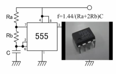
Or we’ve been a tad more old school and used the classic 555 to do it. Or maybe like me, you went through a phase of hacking together Phase Shift and other oscillators because well… it’s fun!

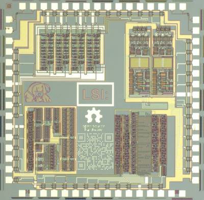
But [Junichi AKITA] has more extreme tastes, deciding that a custom IC layout is the way to go. [Junichi] designed a ring oscillator composed of flip-flops, then hand laid out each MOSFET placing each layer exactly where it should be fabricated.

The resulting design was then fabricated by an academic shuttle service in Japan (a bit like the well known MOSIS service). The result is a tiny circuit in the top right corner of the IC. Which of course [Junichi] then had to wirebond (check the video for a cool 1980s style Westbond machine which are still hugely popular in Japan).

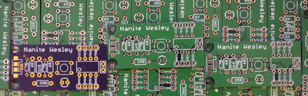
[Junichi] bonded the die directly to a PCB (COB). I assume, purely for irony, a 555, and ATtiny based oscillator were also laid out on the board.
makelsi_icI guess you might have a couple of lingering questions. First you’ll likely bemoan your lack of your own fabrication facility (I’m still eyeing those used 1 micron fab lines that crop up on eBay from time to time). And secondly you might be asking yourself… why?

Both these questions are somewhat answers by the MakeLSI project. This growing project in Japan seems to have opened up semiconductor fabrication to all kinds of projects.

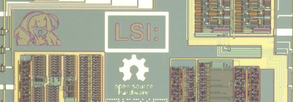
While my Japanese isn’t good enough to fully understand what’s happening it’s clear there are many awesome projects going on. Including joys such as IC layouts designed in vector graphics packages (Inkscape) and die images packed with interesting layouts, anime characters and QR codes.

For more awesome images and information (unfortunately all in Japanese) you can check them out on Facebook or on their homepage.
Continue reading “Blinking An LED – Extreme Edition”

Become Very Unpopular Very Fast With This DIY EMP Generator

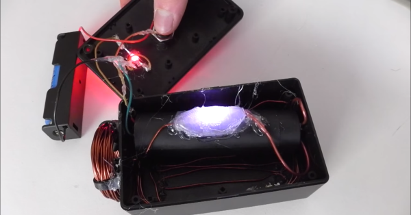
Taking a break from his book, “How to Gain Enemies and Encourage Hostility,” [FPS Weapons] shows us how to build our own handheld EMP generator which can be used to generate immediate dislike from anyone working on something electronic at the hackerspace.

The device is pretty simple. A DC source, in this case an 18650 lithium battery cell, sends power to an “Ultra High Voltage 1000kV Ignition Coil” (as the eBay listing calls it), when a button is pressed. A spark gap is used to dump a large amount of magic pixies into the coil all at once, which generates a strong enough magnetic pulse to induce an unexpected voltage inside of a piece of digital electronics. This usually manages to fire a reset pin or something equivalent, disrupting the device’s normal operation.

While you’re not likely to actually damage anything in a dramatic way with this little EMP, it can still interrupt an important memory write or radio signal and damage it that way. It’s a great way to get the absolute shock of your life if you’re not careful. Either from the HVDC converter or the FCC fines. Video after the break.

Continue reading “Become Very Unpopular Very Fast With This DIY EMP Generator”

Ask Hackaday: DIY Handwriting Recognition

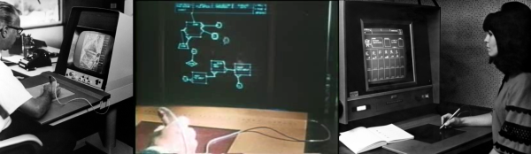
Computer handwriting recognition is very cool by itself, and it’s something that we’d like to incorporate into a project. So we went digging for hacker solutions, and along the way came up with an interesting bit of history and some great algorithms. We feel like we’ve got a good start on that front, but we’re stuck on the hardware tablet sensor itself. So in this Ask Hackaday, we’re going to make the case for why you could be using a tablet-like device for capturing user input or doing handwriting recognition, and then we’re going to ask if you know of any good DIY tablet designs to make it work.

Continue reading “Ask Hackaday: DIY Handwriting Recognition”

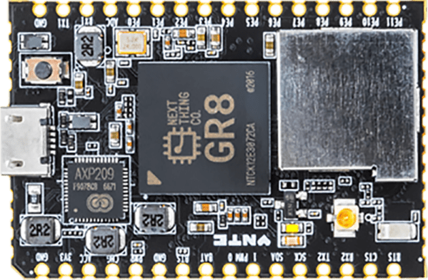
NextThingCo Introduces C.H.I.P. Pro, GR8 System On Module

NextThingCo, makers of the very popular C.H.I.P. single board Linux computer, have released the latest iteration of their hardware. It’s the C.H.I.P. Pro, an SBC designed to be the embedded brains of your next great project, product, or Internet of Things thing.

The C.H.I.P. Pro features an Allwinner R8 ARMv7 Cortex-A8 running at 1 GHz, a MALI-400 GPU, and either 256 MB or 512 MB of NAND Flash. The Pro also features 802.11 b/g/n WiFi, Bluetooth 4.2, and is fully certified by the FCC. This board will be available in December at supposedly any quantity for $16.

The design of the C.H.I.P. Pro is a mix between a module designed to be installed in a product and a single board computer designed for a breadboard. It features castellated edges like hundreds of other modules, but the design means that assembly won’t be as simple as throwing down some paste and reflowing everything. The C.H.I.P. Pro features parts on two sides, making reflow questionable and either 0.1″ headers or a cutout on a PCB necessary. As a single board computer, this thing is small, powerful, and a worthy competitor to the Raspberry Pi Zero. A C.H.I.P. Pro development kit, consisting of two C.H.I.P. Pro units, a ‘debug’ board, and headers for breadboarding, is available for $49, with an estimated ship date in December.

A $16 Linux module with WiFi, Bluetooth, and no NDA is neat, but perhaps a more interesting announcement is that NextThingCo will also be selling the module that powers the C.H.I.P. Pro.

The GR8 module includes an Allwinner R8 ARMv7 Cortex-A8 running at 1 GHz, a MALI-400 GPU, and 256 MB of DDR3 SDRAM. Peripherals include TWI, two UARTS, SPI (SD cards support is hacked onto this), two PWM outputs, a single 6-bit ADC, I2S audio, S/PDIF, one USB 2.0 Host and one USB 2.0 OTG, and a parallel camera interface. This isn’t really a chip meant for video out, but it does support TV out and a parallel LCD interface. A limited datasheet for the GR8 is available on the NextThingCo GitHub.

Putting an entire Linux system on a single BGA module must draw comparisons to the recent release of the Octavo Systems OSD355X family, best known to the Hackaday audiences as the Beaglebone on a chip. Mechanically, the Octavo chip will be a bit easier to solder. Even though it has almost twice as many balls as the GR8, 400 on the Octavo and 252 on the GR8, the Octavo has a much wider pitch between the balls, making escape routing much easier.

Comparing peripherals between the OSD355X and GR8, it’s a bit of a wash, with the OSD coming out slightly ahead with Ethernet, more RAM and fancy TI PRUs. Concerning pricing, the GR8 wins hands down at $6 per chip in any quantity. That’s significantly less than the OSD355X.

The original C.H.I.P. has been exceptionally well received by the community NextThingCo is marketing to, despite the community’s distaste for Allwinner CPUs, cringeworthy PR, and questions concerning the true price of the C.H.I.P.. The C.H.I.P. Pro will surely see more than a few uses, but the GR8 is the real story here. A jellybean part that contains an entire Linux system has been the fevered dream of a madman for years now. The GR8 makes putting the power of open software into any project much easier, and we can’t wait to see the applications it allows.

Creating A PCB In Everything: Friends Don’t Let Friends Use Fritzing

This week, we’re continuing our Creating A PCB In Everything series, where we go through the steps to create a simple, barebones PCB in different EDA suites. We’re done with Eagle, and now it’s time to move onto Fritzing.

fritzing-logoFritzing came out of the Interaction Design Lab at the University of Applied Sciences of Potsdam in 2007 as a project initiated by Professor Reto Wettach, André Knörig and Zach Eveland. It is frequently compared to Processing, Wiring, or Arduino in that it provides an easy way for artists, creatives, or ‘makers’ to dip their toes into the waters of PCB design.
I feel it is necessary to contextualize Fritzing in the space of ‘maker movement’, DIY electronics, and the last decade of Hackaday. Simply by virtue of being an editor for Hackaday, I have seen thousands of homebrew PCBs, and tens of thousands of amateur and hobbyist electronics projects. Despite what the Fritzing’s Wikipedia talk page claims, Fritzing is an important piece of software. The story of the ‘maker movement’ – however ill-defined that phrase is – cannot be told without mentioning Fritzing. It was the inspiration for CircuitLab, and the Fritzing influence can easily be seen in Autodesk’s 123D Circuits.

Just because a piece of software is important doesn’t mean it’s good. I am, perhaps, the world’s leading expert at assessing poorly designed and just plain shitty PCBs. You may scoff at this, but think about it: simply due to my vocation, I look at a lot of PCBs made by amateurs. EE professors, TAs, or Chris Gammell might beat me on volume, but they’re only looking at boards made by students using one tool. I see amateur boards built in every tool, and without exception, the worst are always designed in Fritzing. It should be unacceptable that I can even tell they’re designed in Fritzing.

Fritzing has its place, and that place is building graphical representations for breadboard circuits. Fritzing has no other equal in this respect, and for this purpose, it’s an excellent tool. You can also make a PCB in Fritzing, and here things aren’t as great. I want to do Fritzing for this Creating A PCB In Everything series only to demonstrate how bad PCB design can be.

For the next few thousand words, I am going to combine a tutorial for Fritzing with a review of Fritzing. Fritzing is an important piece of software, if only for being a great way to create graphics of breadboard circuits. As a PCB design tool, it’s lacking; creating parts from scratch is far too hard, and there’s no way to get around the grid snap tool. No one should ever be forced to create a PCB in Fritzing, but it does have its own very limited place.

Continue reading “Creating A PCB In Everything: Friends Don’t Let Friends Use Fritzing”

Porting NES To The ESP32

There’s an elephant in the room when it comes to the Raspberry Pi Zero. The Pi Zero is an immensely popular single board computer, but out of stock issues for the first year may be due to one simple fact: you can run a Nintendo emulator on it. Instead of cool projects like clusters, CNC controllers, and Linux-based throwies, all the potential for the Pi Zero was initially wasted on rescuing the princess.

Espressif has a new chip coming out, the ESP32, and it’s a miraculous Internet of Things thing. It’s cheap, exceptionally powerful, and although we expect the stock issues to be fixed faster than the Pi Zero, there’s still a danger: if the ESP32 can emulate an NES, it may be too popular. This was the hypothetical supply issue I posited in this week’s Hackaday Links post just twenty-four hours ago.

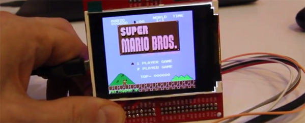
Hackaday fellow, Hackaday Supercon speaker, Espressif employee, and generally awesome dude [Sprite_tm] just ported an NES emulator to the ESP32. It seems Espressif really knows how to sell chips: just give one of your engineers a YouTube channel.

This build began when [Sprite] walked into his office yesterday and found a new board waiting for him to test. This board features the ESP-WROOM-32 module and breaks out a few of the pins to a microSD card, an FT2232 USB/UART module, JTAG support, a bunch of GPIOs, and a 320×240 LCD on the back. [Sprite]’s job for the day was to test this board, but he reads Hackaday with a cup of coffee every morning (like any civilized hacker) and took the links post as a challenge. The result is porting an NES emulator to the ESP32.

The ESP-32-NESEMU is built on the Nofrendo emulator, and when it comes to emulation, the ESP32 is more than capable of keeping the frame rate up. According to [Sprite], the display is the bottleneck; the SPI-powered display doesn’t quite update fast enough. [Sprite] didn’t have enough time to work on the sound, either, but the source for the project is available, even if this dev board isn’t.

Right now, you can order an ESP32; mine are stuck on a container ship a few miles from the port of Long Beach. Supply is still an issue, and now [Sprite] has ensured the ESP32 will be the most popular embedded development platform in recent memory. All of this happened in the space of 24 hours. This is awesome.

Continue reading “Porting NES To The ESP32”

Using The FCC EAS For Fun And Profit

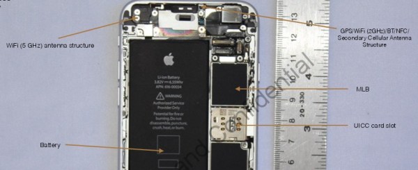
When a consumer electronics device is sold in the US, especially if it has a wireless aspect, it must be tested for compliance with FCC regulations and the test results filed with the FCC (see preparing your product for FCC testing). These documents are then made available online for all to see in the Office of Engineering and Technology (OET) Laboratory Equipment Authorization System (EAS). In fact, it’s this publishing in this and other FCC databases that has led to many leaks about new product releases, some of which we’ve covered, and others we’ve been privileged enough to know about before the filings but whose breaking was forced when the documents were filed, like the Raspberry Pi 3. It turns out that there are a lot of useful things that can be accomplished by poring over FCC filings, and we’ll explore some of them.

Continue reading “Using The FCC EAS For Fun And Profit”