What happens when you break a tap or a bolt in a component whose price tag sits in the tens of thousands. Just drilling it out and throwing in a nut insert stops being acceptable. Is there a way to remove the tap without damaging the master part at all?
Broken tap stuck in the hole it was threading
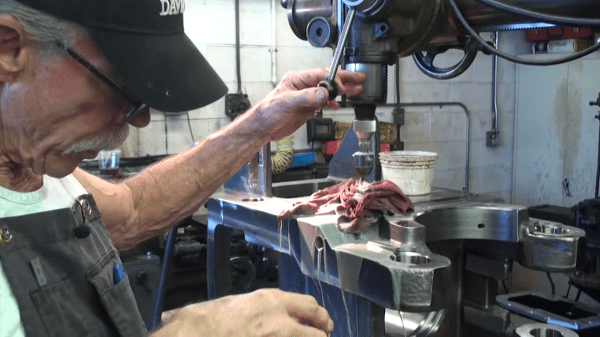
Well, that’s where [Tom Grafton] of Jerry’s Broken Drill and Tap comes in. He’s here to remove taps and chew bubblegum, and he’s definitely chewing bubble gum loudly the whole time. His primary work horse is a Metal Disintegration Machine.
A MDM is basically half of a typical wire EDM set-up. In EDM you used an electrode to punch a hole through the material. Then you thread a wire through the hole, thread it through a sometimes startling array of pulleys, and get going.
[Tom] used the MDM with an appropriately sized electrode to precisely disintegrate the middle of the tap out. After that it’s some careful work with a specially machined magnetic chisel. A quick chase of the threads with a tap and it’s back to the customer.
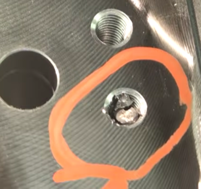
As you can see in the video after the break, the end result is a threaded hole that’s so indistinguishable from the rest he has to mark which one it was; presumably so the customer doesn’t forget why they’re paying him.
A few years ago, [Artem] learned about ways to focus sound in an issue of Popular Mechanics. If sound can be focused, he reasoned, it could be focused onto a plane of microphones. Get enough microphones, and you have a ‘sound camera’, with each microphone a single pixel.
Movies and TV shows about comic books are now the height of culture, so a device using an array of microphones to produce an image isn’t an interesting demonstration of FFT, signal processing, and high-speed electronic design. It’s a Daredevil camera, and it’s one of the greatest builds we’ve ever seen.
[Artem]’s build log isn’t a step-by-step process on how to make a sound camera. Instead, he went through the entire process of building this array of microphones, and like all amazing builds the first step never works. The first prototype was based on a flatbed scanner camera, simply a flatbed scanner in a lightproof box with a pinhole. The idea was, by scanning a microphone back and forth, using the pinhole as a ‘lens’, [Artem] could detect where a sound was coming from. He pulled out his scanner, a signal generator, and ran the experiment. It didn’t work. The box was not soundproof, the inner chamber should have been anechoic, and even if it worked, this camera would only be able to produce an image or two a minute.
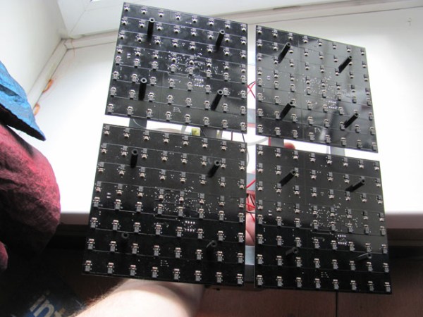
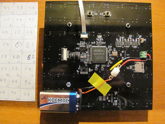
8×8 microphone array (mics on opposite side) connected to Altera FPGA at the center
The idea sat in the shelf of [Artem]’s mind for a while, and along the way he learned about FFT and how the gigantic Duga over the horizon radar actually worked. Math was the answer, and by using FFT to transform a microphones signals from up-and-down to buckets of frequency and intensity, he could build this camera.
That was the theory, anyway. Practicality has a way of getting in the way, and to build this gigantic sound camera he would need dozens of microphones, dozens of amplifiers, and a controller with enough analog pins, DACs, and processing power to make sense of all of this.
This complexity collapsed when [Artem] realized there was an off-the-shelf part that was a perfect microphone camera pixel. MEMS microphones, like the kind found in smartphones, take analog sound and turn it into a digital signal. Feed this into a fast enough microcontroller, and you can perform FFT on the signal and repeat the same process on the next pixel. This was the answer, and the only thing left to do was to build a board with an array of microphones.
[Artem]’s camera microphone is constructed out of several modules, each of them consisting of an 8×8 array of MEMS microphones, controlled via FPGA. These individual modules can be chained together, and the ‘big build’ is a 32×32 array. After a few problems with manufacturing, the board actually worked. He was recording 64 channels of audio from a single panel. Turning on the FFT visualization and pointing it at a speaker revealed that yes, he had indeed made a sound camera.
The result is a terribly crude movie with blobs of color, but that’s the reality of a camera that only has 32×32 resolution. Right now the sound camera works, the images are crude, and [Artem] has a few ideas of where to go next. A cheap PC is fast enough to record and process all the data, but now it’s an issue of bandwidth; 30 sounds per second is a total of 64 Mbps of data. That’s doable, but it would need another FPGA implementation.
Is this sonic vision? Yes, technically the board works. No, in that the project is stalled, and it’s expensive by any electronic hobbyist standards. Still, it’s one of the best to grace our front page.
[jamesone111] bought a Transcend WifiSD card, presumably for photography, but it may just have been because he heard that they’re actually tiny Linux servers.
He read a post about these cards on the OpenWRT forums. They’re all a similar configuration of a relatively large amount of memory (compared to the usual embedded computer), a WiFi chip, and an ARM processor running a tiny Linux install. The card acts as a WiFi access point with a little server running on it, and waits for the user to connect to it via a website. It also has a mode where it will connect to up to three access points specified by the user, but it doesn’t actually have a way to tell the user what its IP address is; which is kind of funny.
[jamesone111] hacked around with the Transcend card for a bit. He found it pretty insecure, which as long as you’re not a naked celebrity, shouldn’t be a huge issue. For the hacker this is great as it opens up the chance of hacking the firmware for other uses.
Some have already pulled off some cool hacks with these cards. For example, [peterburk] hacked a similar card by PQI to turn his iPod into a portable file server.
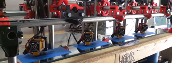
3D printers are great for producing one thing, but if you need multiple copies, the workflow quickly starts to go downhill. The solution? Build a 3D printer with multiple print heads, capable of printing four objects in the same amount of time it takes to print one.
This build is an experiment for [allted]’ Mostly Printed CNC / MultiTool. It’s a CNC machine that uses printed parts and 3/4″ electrical conduit for the frame and rails. That last bit is the interesting part: electrical conduit is cheap, easy to acquire, available everywhere, and can be cut with a hacksaw. As far as desktop CNC machines go, it doesn’t get simpler or cheaper than this, and a few of these builds are milling wood with the same quality of a machine based on linear rails. It won the grand prize in the recent Boca Bearings contest, and is a great basis for a cheap and serviceable 2.5 or 3D CNC.
[allted] already has this cheap CNC mill cutting aluminum and engraving wood with a laser, showing off the capabilities of a remarkably cheap but highly expandable CNC machine. It’s a fantastic build, and we can’t wait to see more of these machines pop up in garages and workspaces.
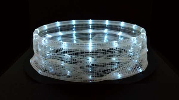
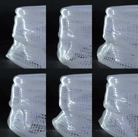
This fascinating project manages to be both something new and something old done in a new way. Artist [Akinori Goto] has used 3D printing to create a sort of frameless zoetrope. It consists of a short animation of a human figure, but the 3D movements of that figure through time are “smeared” across a circular zone – instead of the movements of the figure being captured as individual figures or frames, they are combined into a single object, in a way squashing 4 dimensions into 3.
“Slices” of that object, when illuminated by a thin shaft of light, reveal the figure’s pose at a particular moment in time. When the object is spun while illuminated in this way, the figure appears to be animated in a manner very similar to a zoetrope.
There are two versions from [Akinori Goto] that we were able to find. The one shown above is a human figure walking, but there is a more recent and more ambitious version showing a dancer in motion, embedded below.
Since a thin ray of light is used to illuminate a single slice of the sculpture at a time, it’s also possible to use multiple points of illumination – or even move them – for different visual effects. Check out the videos below to see these in action.
In the last episode, we put our circuit boards through the reflow process. Unfortunately, it’s not 100% accurate, and there are often problems that can occur that need to be detected and fixed. That’s what the inspection step is for. One could insert an inspection step after paste, after placement, and after reflow, but the first two are icing on the cake — the phase where most mistakes can be caught is after reflow.
Homebrew laser cutters are nifty devices, but scorching your pals, burning the house down, or smelling up the neighborhood isn’t anyone’s idea of a great time. Lets face it. A 60-watt laser that can cut plastics offers far more trouble than even the crankiest 3D-printers (unless, of course, our 3D printed spaghetti comes to life and decides to terrorize the neighborhood). Sure, a laser’s focused beam is usually pointed in the right direction while cutting, but even an unfocused beam that reflects off a shiny material can start fires. What’s more, since most materials burn, rather than simply melt, a host of awful fumes spew from every cut.
Despite the danger, the temptation to build one is irresistible. With tubes, power supplies, and water coolers now in abundance from overseas re-sellers, the parts are just a PayPal-push away from landing on our doorsteps. We’ve also seen a host of exciting builds come together on the dining room table. Our table could be riddled with laser parts too! After combing through countless laser build logs, I’ve yet to encounter the definitive guide that tells us how to take the proper first steps forward in keeping ourselves safe while building our own laser cutter. Perhaps that knowledge is implicit to the community, scattered on forums; or perhaps it’s learned by each brave designer on their own from one-too-many close calls. Neither of these options seems fair to the laser newb, so I decided to lay down the law here.

 [Artem]’s camera microphone is constructed out of several modules, each of them consisting of an 8×8 array of MEMS microphones, controlled via FPGA. These individual modules can be chained together, and the ‘big build’ is a 32×32 array. After a few problems with manufacturing, the board actually worked. He was recording 64 channels of audio from a single panel. Turning on the FFT visualization and pointing it at a speaker revealed that yes, he had indeed made a sound camera.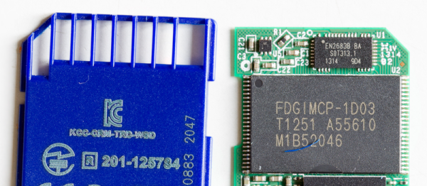
 “Slices” of that object, when illuminated by a thin shaft of light, reveal the figure’s pose at a particular moment in time. When the object is spun while illuminated in this way, the figure appears to be animated in a manner very similar to a