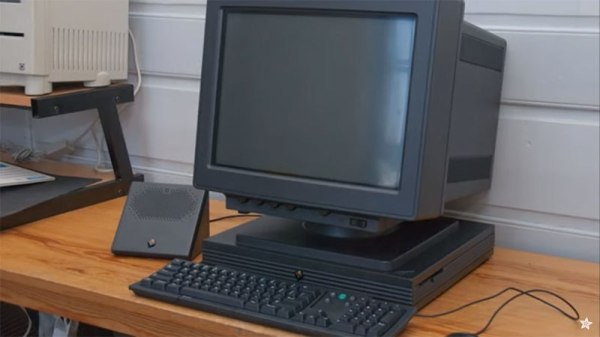
From the late 80s to the early 90s, [Steve Jobs] wasn’t at Apple. He built another company in the meantime, NeXT Computer, a company that introduced jet black workstations to universities and institutions, developed an incredible emphasis on object-oriented programming, and laid the groundwork for the Unix-ey flavor of Apple’s OS X. Coincidently, there is a lot of old NeXT gear at the Adafruit clubhouse – not that there’s anything wrong with that, we all have our own strange affectations and proclivities. Recently, [Lady Ada] turned one of the strangest components of the NeXT computer ecosystem into something useful: a computer speaker.
The item in question for this build is the NeXT ‘sound box’. When not using the very special NeXT monitor, the NeXT computer connects the monitor, keyboard, and speakers through this odd little box. There are two versions of the NeXT sound box, and peripherals from either version are incompatible with each other. ([Jobs] was known for his sense of design and a desire for a simplified user experience, you know.)
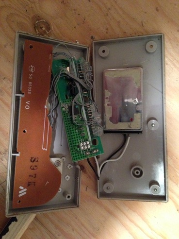
In [Lady Ada]’s initial teardown of the sound box, she discovers a few interesting things about this peripheral. There’s an I2S DAC inside there, connected to an unobtanium DB19 connector. Theoretically, that I2S device could be used to drive the speaker with digital audio. The only problem is the DB19 connector – they’re rare, and [Steve] from Big Mess o’ Wires bought the world’s supply.
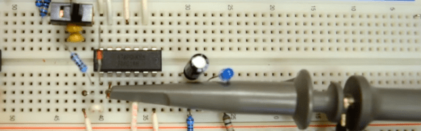
Without these connectors, and since it’s only an hour-long show, [Lady Ada] went with the most effective hack. She grabbed a USB audio dongle/card, added a small amplifier, and soldered a few wires onto the power and ground pins of an IC. It’s simple, effective, fast, and turns an awesome looking 30-year-old peripheral into a useful device.