Scotty Allen’s PCB Fab Tour Is Like Willy Wonka’s For Hardware Geeks

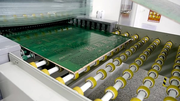
The availability of low-cost, insanely high-quality PCBs has really changed how we do electronics. Here at Hackaday we see people ditching home fabrication with increasing frequency, and going to small-run fab for their prototypes and projects. Today you can get a look at the types of factory processes that make that possible. [Scotty Allen] just published a (sponsored) tour of a PCB fab house that shows off the incredible machine tools and chemical baths that are never pondered by the world’s electronics consumers. If you have an appreciation PCBs, it’s a joy to follow a design through the process so take your coffee break and let this video roll.

Several parts of this will be very familiar. The photo-resist and etching process for 2-layer boards is more or less the same as it would be in your own workshop. Of course the panels are much larger than you’d ever try at home, and they’re not using a food storage container and homemade etchant. In fact the processes are by and large automated which makes sense considering the volume a factory like this is churning through. Even moving stacks of boards around the factory is show with automated trolleys.

Six headed PCB drilling machine (four heads in use here).

What we find most interesting about this tour is the multi-layer board process, the drilling machines, and the solder mask application. For boards that use more than two layers, the designs are built from the inside out, adding substrate and copper foil layers as they go. It’s neat to watch but we’re still left wondering how the inner layers are aligned with the outer. If you have insight on this please sound off in the comments below.

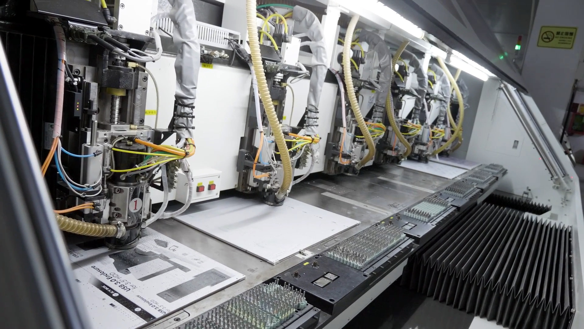
The drilling process isn’t so much a surprise as it is a marvel to see huge machines with six drill heads working on multiple boards at one time. It sure beats a Dremel drill press. The solder mask process is one that we don’t often see shown off. The ink for the mask is applied to the entire board and baked just to make it tacky. A photo process is then utilized which works much in the same way photoresist works for copper etching. Transparent film with patterns printed on it cures the solder mask that should stay, while the rest is washed away in the next step.

Boards continue through the process to get silk screen, surface treatment, and routing to separate individual boards from panels. Electrical testing is performed and the candy making PCB fab process is complete. From start to finish, seeing the consistency and speed of each step is very satisfying.

Looking to do a big run of boards? You may find [Brian Benchoff’s] panelization guide of interest.

Continue reading “Scotty Allen’s PCB Fab Tour Is Like Willy Wonka’s For Hardware Geeks”

Building A Knife By Hand Is Just As Hard As You Think

Carl Sagan once said: “If you wish to make an apple pie from scratch, you must first invent the universe.” In other words, the term “scratch” is really a relative sort of thing. Did you grow the apples? Did you plant the wheat to make the flour? Where do you keep your windmill, incidentally? With Carl’s words in mind, we suppose we can’t say that [Flannagill] truly built this incredible knife from scratch, after all, he ordered the sheet steel on Amazon. But we think it’s close enough.

He was kind enough to document the epic build in fantastic detail, including (crucially), the missteps he made along the way. While none of the mistakes were big enough to derail the project, he mentions a few instances where he wasted time and money trying to take shortcuts. Even if making your own knives at home isn’t on your short list of summer projects, we’d wager there’s something in this build log you can learn from regardless.

So how does one build a knife? Slowly and methodically, if what [Flannagill] has written up is any indication. It started with a sketch of the knife on a piece of paper, the outline of which was then transferred to a piece of tool steel with nothing more exotic than a permanent marker. An angle grinder was then used to follow the outline and create the rough shape of the final knife.

From there, the process is done almost entirely with hand files. Here [Flannagill] gives one of his most important pieces of advice: don’t cheap out on the tools. He bought the cheapest set of files he could, and paid the price: he says it took up to 14 hours to complete just one side of the knife. Once he switched over to higher quality files, the rest of the work went much faster.

After filing and sanding the knife blank, it went into a charcoal fire to be hardened, followed by a total of 4 hours in a 200 C (~400 F) oven to heat temper it. Finally the handle pieces (which are officially known as “scales”) were attached, and finished with considerably less labor intensive woodworking methods. The final result is a gorgeous one of a kind specimen that [Flannagill] is rightly very proud of.

If you’re worried this process looks a bit too quick and easy for you, don’t worry. You can always go the [Bil Herd] route and make a forge out of your old sink if you’d rather start your apple pie a bit closer to the tree.

Mechanisms: Abrasives

In our “Mechanisms” series, we’ve featured the fascinating bits and pieces that go into making our mechanical world work. From simple machines such as screws and levers, from springs to couplings, and even more complex mechanisms like zippers and solenoids, we’ve covered the gamut. But we haven’t talked about one of the very earliest mechanisms, captured from nature by our clever ancestors to do useful work like grinding grain and shaping materials into tools: grit, sand, abrasives.

Continue reading “Mechanisms: Abrasives”

GPS Disciplined Oscillators

[Martin Lorton] acquired a GPS-disciplined oscillator. He wasn’t quite sure what to do with it, so he did a little research and experimentation. If you have about two hours to spare, you can watch his videos where he shares his results (see below).

The unit he mainly looks at is a Symmetricom TrueTime XL-DC, and even on eBay it ran over $500. However, [Martin] also looks at a smaller unit that is much more affordable.

Continue reading “GPS Disciplined Oscillators”

Hackaday guide to Lathes

Preparing For A Lathe: How To Move 3000 Pounds Of Iron

You say to yourself, “Self, I want, nay, need a lathe”. Being a good little trooper, you then did all your research, having chosen Import or American, Imperial or Metric, and all your feed options and such. You then pulled the trigger and the machine is en route to your shop. Now what?

Continue reading “Preparing For A Lathe: How To Move 3000 Pounds Of Iron”

Flash Your Libre Firmware With A Libre Programmer

Whether or not you personally agree with all the ideals of the Free Software Foundation (FSF), you’ve got to give them credit: they don’t mess around. They started by laying the groundwork for a free and open source operating system, then once that dream was realized, started pushing the idea of replacing proprietary BIOS firmware with an open alternative such as Libreboot. But apparently, even that’s not enough, as there’s still more freedom to be had. We’re playing 4D Libre Chess now, folks.

To flash your libre boot firmware on your libre OS running computer without any proprietary funny business, you’re going to need a libre chip programmer. Luckily, the FSF has just awarded the Zerocat Chipflasher their “Respects Your Freedom” certification, meaning every element of the product is released under a free license for your hacking enjoyment. According to the FSF, this is a major milestone towards their goal of providing users a truly free and open source computer, from the browser all the way down to the BIOS.

Of course, you don’t need to be Richard Stallman to appreciate a fully open chip programmer. With the software, wiring diagrams, and PCB files available on the Chipflasher’s website, the project is an excellent educational reference. Is also means that with a clone the Chipflasher’s Git repository, you’re well on the way to spinning up your own build of the device.

Given the roughly $350 USD price tag on the first generation Zerocat Chipflasher, it seems fairly likely we’ll be seeing some DIY builds of this device before too long. Not that we want to deprive Zerocat commercial success for this very neat piece of gear, but for many it’s a mighty steep price; even if you do get all the Freedoms.

It may use a device of slightly more nebulous morality than the Zerocat Chipflasher, but our own [Bryan Cockfield] documented the saga of getting Libreboot installed on a Thinkpad X200 if you’d like to know more about the high stakes world of BIOS replacement. Whatever it takes to get that Intel Management Engine off your penguin-powered box.

An Oscilloscope For The Nuclear Age

Here at Hackaday, we’re suckers for vintage instruments. More than one of our staffers has a bench adorned with devices spanning many decades, and there’s nothing more we like reading about that excursions into the more interesting or unusual examples. So when a Tweet comes our way talking about a very special oscilloscope, of course we have to take a look! The Tektronix 519 from 1962 has a 1GHz bandwidth, and [Timothy Koeth] has two of them in his collection. His description may be a year or two old, but this is the kind of device for which the up-to-the-minute doesn’t matter.

A modern 1GHz oscilloscope is hardly cheap, but is substantially a higher-speed version of the run-of-the-mill ‘scope you probably have on your bench. Its 1962 equivalent comes from a time when GHz broadband amplifiers for an oscilloscope input were the stuff of science fiction. The 519 takes the novel approach of eschewing amplification or signal conditioning and taking the input directly to the CRT deflection plates. It thus has a highly unusual 125Ω input impedance, and its feed passes through a coiled coaxial delay line to give the trigger circuits time to do their job before going into the CRT and then emerging from it for termination. It thus has a fixed deflection in volts per centimeter rather than millivolts, and each instrument has the calibration of its CRT embossed upon its bezel.

The 519 would not have been a cheap instrument in 1962, and it is no accident that there are reports of many of them coming back to Tek for service with radioactive contamination from their use in Government projects. We can’t help wondering whether the Russian equivalent super-high-speed ‘scope used the same approach, though we suspect we’ll never know.

If vintage Tek is your thing, have a look at their PCB manufacture from the 1960s.

Thanks [Luke Weston] for the tip.