Need to do some real fine power consumption measurements? [Gero Müller] was in that exact situation, and wasn’t happy with the expensive off-the-shelf tools for doing the job. Thus, he built his own. Meet nanoTracer.
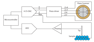
The concept of the device is simple. It’s a power supply that measures current on a nanoampere scale, and on microsecond intervals. It can deliver from 0 to 5.125 volts in 256 steps, and up to 100 mA of current. It has a sampling bandwidth of 1 MHz, at 2 million samples per second, with effective dynamic range from 100 mA all the way down to 100 nA. For capturing microscopic changes in current draw, that’s invaluable. The device also features a UART for talking to an attached project directly, and additional pins for taking further ADC measurements where needed.
Right now, it’s at an early prototype stage, and [Gero] tells us the software is “very basic” right now. Still, it’s easy to see how this device would be very useful to anyone working to optimize power consumption on low-power projects. One wonders if there are some applications in power-based side-channel attacks, too.
We’re hoping to learn more about nanoTracer from [Gero] soon—how it was built, how it works, and what it’s really like to use. Perhaps one day down the line, the design might even become available for others that could use such a nifty tool. There’s no mucking about when you get down to nanoamps, after all. If you’ve cooked up something similar in your own lab, don’t hesitate to let us know!