Homebrew Tire Inflator Pushes The Limits Of PVC Construction

Let’s just clear something up right from the start with this one: there’s literally no reason to build your own tire inflator from scratch, especially when you can buy a perfectly serviceable one for not a lot of money. But that’s missing the point of this build entirely, and thinking that way risks passing up yet another fascinating build from PVC virtuoso [Vang Hà], which would be a shame

The chances are most of you will recall [Vang Hà]’s super-detailed working PVC model excavator, and while we’re tempted to say this simple air pump is a step toward more practical PVC builds, the fact remains that the excavator was a working model with a completely homebrew hydraulic system. As usual, PVC is the favored material, with sheet stock harvested from sections of flattened pipe. Only the simplest of tools are used, with a hand drill standing in for a lathe to make such precision components as the compressor piston. There are some great ideas here, like using Schrader tire valves as the intake and exhaust valves on the pump cylinder. And that’s not to mention the assembly tips, like making a hermetic seal between the metal valves and the PVC manifold by reaming out a hole with a heated drill bit.

We’re not sure how much abuse a plastic compressor like this will stand up to, but then again, we’ve seen some commercially available tire inflators with far, far less robust internals than this one.

Continue reading “Homebrew Tire Inflator Pushes The Limits Of PVC Construction”

Vintage Tektronix Virtual Graticule

Oscilloscopes are great for measuring the time and voltage information of a signal. Some old scopes don’t have much in the way of markings on the CRT, although eventually, we started seeing scales that allowed you to count squares easily. Early scopes had marks on the glass or plastic over the CRT, but as [Vintage TEK Museum] points out, this meant for best accuracy, you had to look directly at the CRT. If you were at an angle horizontally or vertically, the position of the trace would appear to move concerning the lines on the screen. You can see the effect in the video below.

The simple solution was to mark directly into the phosphor, which minimized the effect. Before that was possible, [Bob Anderson] invented a clever solution, although Tektronix didn’t produce any scopes using it for some reason. The idea was the virtual oscilloscope graticule, and it was quite clever.

The idea was to put the graticule on a semi-reflective mirror. Looking through the assembly, you would actually see the trace and the reflection of the graticule in the mirror. The resulting image is perfectly aligned if the assembly is constructed properly. You can, at some angles, see both the front and reflected graticules.

According to the video, management was not impressed because someone other than [Anderson] showed a poor-quality prototype to them. By 1962, the graticule in the phosphor took over, and there was no need for [Anderson’s] clever invention.

These days, a graticule is just bits on the screen. Even if you roll your own.

Continue reading “Vintage Tektronix Virtual Graticule”

3D-Printed Shredder Eats Lettuce For Breakfast

Shredding things isn’t just good for efficiently and securely disposing of them. It’s also very fun, as well. [Joonas] of [Let’s Print] didn’t have a shredder, so set about 3D printing one of their very own.

The design apes that of the big metal trash shredders you’ve probably seen in videos all over the internet. They use a pair of counter-rotating drums with big teeth. As the drums turn, the teeth grab and pull objects into the gap between the drums, where they are duly torn apart into smaller pieces.

In this design, plastic drums are pressed into service as [Joonas] does not have a metal 3D printer. A brushed DC motor is used to drive the shredder. A large multi-stage gearbox is used to step down the motor’s output and provide plenty of torque to do the job.

The shredder gets tested with plenty of amusing garbage. Everything from old vegetables, to paper, and rock-hard old cheeseburgers are put through the machine. It does an able job in all cases, though obviously the plastic drums can’t handle the same kind of jobs as a proper metal shredder. Harder plastics and aluminium cans stall out the shredder, though. The gearbox also tends to strip gears on the tougher stuff. The basic theory is sound, but some upgrades could really make this thing shine.

Is it a device that will see a lot of practical use? Perhaps not. Is it a fun device that would be the star of your next hackerspace Show and Tell? Absolutely. Plus it might be a great way to get rid of lots of those unfinished projects that always clog up your storage areas, too! Video after the break.

Continue reading “3D-Printed Shredder Eats Lettuce For Breakfast”

Finessing A Soldering Iron To Remove Large Connectors

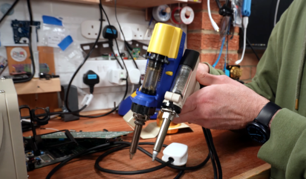
One of the first tools that is added to a toolbox when working on electronics, perhaps besides a multimeter, is a soldering iron. From there, soldering tools can be added as needed such as a hot air gun, reflow oven, soldering gun, or desoldering pump. But often a soldering iron is all that’s needed even for some specialized tasks as [Mr SolderFix] demonstrates.

This specific technique involves removing a large connector from a PCB. Typically either a heat gun would be used, which might damage the PCB, or a tedious process involving a desoldering tool or braided wick might be tried. But with just a soldering iron, a few pieces of wire can be soldered around each of the pins to create a massive solder blob which connects all the pins of the connector to this wire. With everything connected to solder and wire, the soldering iron is simply pressed into this amalgamation and the connector will fall right out of the board, and the wire can simply be dropped away from the PCB along with most of the solder.

There is some cleanup work to do afterwards, especially removing excess solder in the holes in the PCB, but it’s nothing a little wick and effort can’t take care of. Compared to other methods which might require specialized tools or a lot more time, this is quite the technique to add to one’s soldering repertoire. For some more advanced desoldering techniques, take a look at this method for saving PCBs from some thermal stresses.

Continue reading “Finessing A Soldering Iron To Remove Large Connectors”

Laser And Webcam Team Up For Micron-Resolution Flatness Measurements

When you want to measure the length, breadth, or depth of an object, there are plenty of instruments for the job. You can start with a tape measure, move up to calipers if you need more precision, or maybe even a micrometer if it’s a really critical dimension. But what if you want to know how flat something is? Is there something other than a straightedge and an eyeball for assessing the flatness of a surface?

As it turns out, there is: a $15 webcam and a cheap laser level will do the job, along with some homebrew software and a little bit of patience. At least that’s what [Bryan Howard] came up with to help him assess the flatness of the gantry he fabricated for a large CNC machine he’s working on.

The gantry arm is built from steel tubing, a commodity product with plenty of dimensional variability. To measure the microscopic hills and valleys over the length of the beam, [Bryan] mounted a lens-less webcam to a block of metal. A cheap laser level is set up to skim over the top of the beam and shine across the camera’s image sensor.

On a laptop, images of the beam are converted into an intensity profile whose peak is located by a Gaussian curve fit. The location of the peak on the sensor is recorded at various points along the surface, leading to a map of the microscopic hills and valleys along the beam.

As seen in the video after the break, [Bryan]’s results from such a quick-and-dirty setup are impressive. Despite some wobblies in the laser beam thanks to its auto-leveling mechanism, he was able to scan the entire length of the beam, which looks like it’s more than a meter long, and measure the flatness with a resolution of a couple of microns. Spoiler alert: the beam needs some work. But now [Bryan] knows just where to scrape and shim the surface and by how much, which is a whole lot better than guessing.   Continue reading “Laser And Webcam Team Up For Micron-Resolution Flatness Measurements”

Spin Up To Speed With This Stroboscope

A stroboscope is not the most common tool, and while they can be purchased fairly inexpensively from various online stores, they are straightforward enough tools that plenty of us could build our own mostly from parts laying around. The basic idea is to shine a flashing light on a spinning object, and when it appears stationary the stroboscope will indicate the rotational speed. There are a few specialty parts that might not be in everyone’s parts drawers, though, and [John] shows us the ins-and-outs of his own DIY stroboscope.

The effect relies on extremely precise timing, and as such the most important part of a build like this is making sure to get the LED circuitry correct so its duty cycle and frequency can be tightly controlled. [John] is using a PT4115E driver board for the LED, and is using it to power a 1W white LED which also includes its own heat sink and lens. The controls for the stroboscope are handled by an ATtiny1614 microcontroller which shows its pulse rate on a small screen. The user can control the rate the LED flashes with simple controls, and when the spinning object appears to come to a stop the only thing left to do is read this value off of the screen.

While it might seem like an overly niche tool, stroboscopes have plenty of day-to-day uses. Older cars that used a central distributor made use of a specialty stroboscope called a timing light in order to properly advance the ignition timing of the engine. They also retain some use in medical applications, and plenty of older readers may be familiar with their use adjusting the speed on record players. They can also be used to make sure the shutter speeds on cameras are calibrated correctly.

Continue reading “Spin Up To Speed With This Stroboscope”

Pocket-Sized Thermal Imager

Just as the gold standard for multimeters and other instrumentation likely comes in a yellow package of some sort, there is a similar household name for thermal imaging. But, if they’re known for anything other than the highest quality thermal cameras, it’s excessively high price. There are other options around but if you want to make sure that the finished product has some sort of quality control you might want to consider building your own thermal imaging device like [Ruslan] has done here.

The pocket-sized thermal camera is built around a MLX90640 sensor from Melexis which can be obtained on its own, but can also be paired with an STM32F446 board with a USB connection in order to easily connect it to a computer. For that, [Ruslan] paired it with an ESP32 board with a companion screen, so that the entire package could be assembled together with a battery and still maintain its sleek shape. The data coming from the thermal imagining sensor does need some post-processing in order to display useful images, but this is well within the capabilities of the STM32 and ESP32.

With an operating time on battery of over eight hours and a weight under 100 grams, this could be just the thing for someone looking for a thermal camera who doesn’t want to give up an arm and a leg to one of the industry giants. If you’re looking for something even simpler, we’ve seen a thermal camera based on a Raspberry Pi that delivers its images over the network instead of on its own screen.