Flashing your code into an Arduino, an ESP32 or any other modern microcontroller platform is pretty straightforward: connect the device through USB, fire up the appropriate software platform, and press “program”. But those who followed embedded programming classes in the ’80s and ’90s will remember a more complicated procedure that consists of swapping EPROM chips between a programmer, a target board and a UV eraser. Veterans of that era might even remember how you could overwrite a previous program with NOPs and place new code behind it, to save yourself a trip to the “blank chips” bin.
If you’re a retrocomputer enthusiast and would like to have the easy programming of modern tools, but the authenticity of a self-contained ROM-loading computer, you might want to check out [Anders Nielsen]’s latest design of a wireless boot loader for a 6502 single board computer. The target platform for this project is a beautiful custom-made 6502-based retrocomputer that [Anders] documented in detail on his Hackaday.io page.
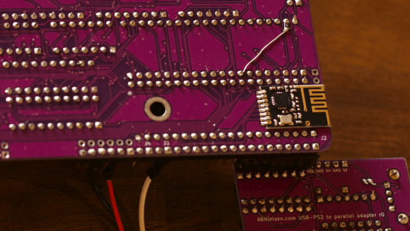
The basic idea here is to have a wireless receiver on the target system that receives data from a transmitter connected to a modern PC. When you click “program”, the object code is sent to the 6502 machine, stored in RAM and executed. The wireless link is implemented with a pair of nRF24L01 2.4 GHz modules that communicate through SPI. Since [Anders]’s Mac Mini doesn’t come with GPIO ports he hooked up the transmitter to a Raspberry Pi which he controlled through a network link.
On the 6502 side he wrote a bootloader in assembly language, which bit-bangs the SPI protocol to communicate with the wireless module. A simple user interface is included to allow the user to control the loading and running of programs. All code and hardware documentation is available on Github for use by anyone with a similar 6502 system.
Those nRF24L01s are versatile little things: we’ve seen them being used to transfer anything from MIDI data to TCP/IP links, as well as code for other microcontroller platforms.
Continue reading “Wireless Bootloader Saves You From Swapping ROM Chips”