We’ve featured a number of people who’ve taken the plunge and created their own customized keyboard; at this point it’s safe to say that there’s enough information and source code out there that anyone who’s looking to build their own board won’t have much trouble figuring out how to do so. That being said, it’s nice to have a comprehensive at a process from start to finish. Why sift through forum posts and image galleries looking for crumbs if you don’t have to?
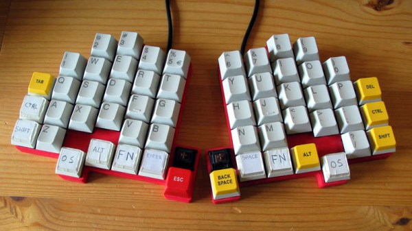
 That’s precisely what makes this write-up by [Maarten Tromp] so interesting. He walks the reader through every step of the design and creation of his customized keyboard, from coming up with the rather unique layout to writing the firmware for its AVR microcontroller. It’s a long read, filled with plenty of tips and tricks from a multitude of disciplines.
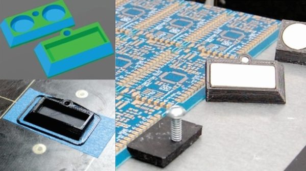
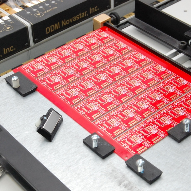
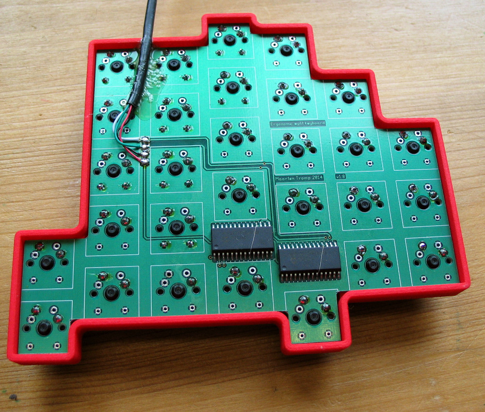
After looking at other custom boards for inspiration, [Maarten] used OpenSCAD to create a 3D model of his proposed design, and had it printed at Shapeways. His electronics are based around an Atmel ATMega328P using vUSB, and Microchip MCP23017 I/O expanders to connect all the keys. He wrapped it all up by designing a PCB in gEDA PCB and having it sent off for production. As a testament to his attention to detail, everything mated up on the first try.
[Maarten] is happy with the final product, but mentions that in a future revision he would like to add RGB lighting and use a microcontroller that has native USB support. He’d also like to drop the I/O expanders and switch over to Charlieplexing for the key matrix.
From uncommon layouts to diminutive technicolor beauties, it seems there’s no end of custom keyboards in sight. We aren’t complaining.