Thorough Macbook Charger Teardown Reveals Some Complex Circuitry

Apple has a reputation in the tech world as being overpriced, and nowhere is that perception more common than in the Hackaday comments. The standard argument, of course, is that for a device with equivalent specs, Apple charges a lot more than its competitors. That argument is not without its flaws, especially when you consider factors other than simple specs like RAM and processor speed, and take into account materials used and build quality. But, as this teardown by [Ken Shirriff] shows, Apple’s attention to detail extends beyond simply machining Macbook bodies out of aluminum.

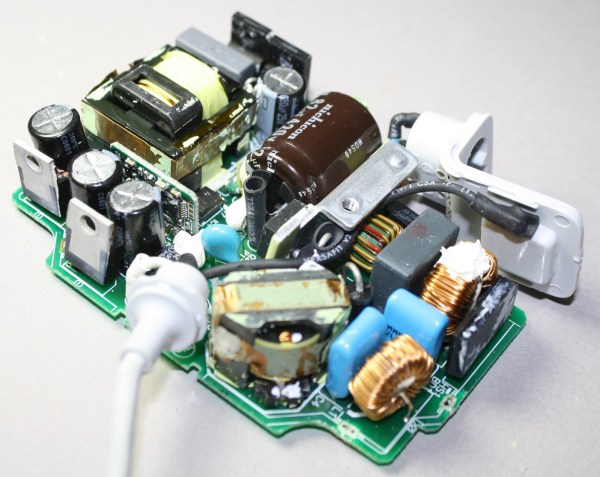
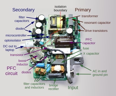
In his teardown, [Ken Shirriff] thoroughly investigates and describes all of the components and circuitry that go into the ubiquitous Macbook charger. Why does it cost $79? Other than the MagSafe connector, what makes it any better than the charger that came with your Toshiba Satellite in the ’90s? Isn’t it just a transformer to convert AC power to DC?

components1

[Ken Shirriff] answers all of this and more, and you may be surprised by what he found. As it turns out, the Macbook charger isn’t just a transformer in a plastic case with a fancy magnetic connector. There is a lot of high-quality circuitry involved to make the power output as clean and stable as possible, and to avoid potential damage to your Macbook that could be caused by dirty power or voltage spikes. Does it justify the costs, even with so many reported failures? That’s for you to decide, but there is no questioning that Apple put more thought into their chargers than simply converting AC to DC.

Monsieur Adaptateur: Jacques Of All Connector Trades

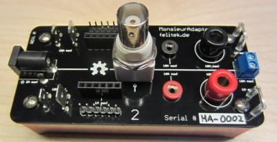
It seems that any time you have a circuit on the bench, there’s wires. Lots of wires. If you are working on something new, it is a good bet that some of those wires are clipped to other wires using some field expedient, especially the power wires. We often have an alligator clip awkwardly grabbing the shell of a BNC. [Felicitus] got tired of this, so he created Monsieur Adaptateur, a breakout board that has common connectors you’ll need when working on a prototype.

What kind of connectors?mafull

  • DC Jack 2.1mm
  • 2mm Jacks
  • 4mm Jacks
  • BNC Connector
  • Terminal Block
  • Scope probe connector
  • Standard 6 pin 0.1″ female header
  • Standard 6 pin 0.1″ male header
  • 4.75 and 6.3mm blade connectors

The dual conductor items (like the 2.1mm jack and the BNC) connect to both sides of the board. The other connectors are in pairs. The idea is you can connect, for example, a BNC cable from a signal generator to some jumper wires on the male header, connect the scope to the scope probe connector, and still have the banana jacks to hook up, say, a digital meter.

No one would say this is going to change the world, but this is one of those things that is simple, but very useful. The plans are all on Github, and obviously you could adapt it with connectors that make sense for your specific situation.

Continue reading “Monsieur Adaptateur: Jacques Of All Connector Trades”

iram

PCI I-RAM Working Without A PCI Slot

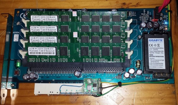
[Gnif] had a recent hard drive failure in his home server. When rebuilding his RAID array, he decided to update to the ZFS file system. While researching ZFS, [Gnif] learned that the file system allows for a small USB cache disk to greatly improve his disk performance. Since USB is rather slow, [Gnif] had an idea to try to use an old i-RAM PCI card instead.

The problem was that he didn’t have any free PCI slots left in his home server. It didn’t take long for [Gnif] to realize that the PCI card was only using the PCI slot for power. All of the data transfer is actually done via a SATA cable. [Gnif] decided that he could likely get by without an actual PCI slot with just a bit of hacking.

[Gnif] desoldered a PCI socket from an old faulty motherboard, losing half of the pins in the process. Luckily, the pins he needed still remained. [Gnif] knew that DDR memory can be very power-hungry. This meant that he couldn’t only solder one wire for each of the 3v, 5v, 12v, and ground pins. He had to connect all of them in order to share the current load. All in all, this ended up being about 20 pins. He later tested the current draw and found it reached as high as 1.2 amps, confirming his earlier decision. Finally, the reset pin needed to be pulled to 3.3V in order to make the disk accessible.

All of the wires from his adapter were run to Molex connectors. This allows [Gnif] to power the device from a computer power supply. All of the connections were covered in hot glue to prevent them from wriggling lose.

Vacuum Tube

Vacuum Tube Repair After A Spectacular Failure

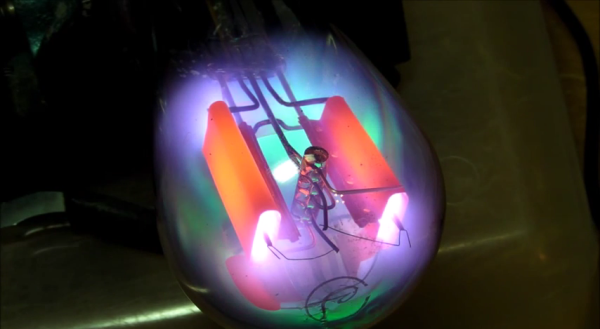
[Eric] has an Atwater Kent 55C AM radio from the early 1900’s. He’s been trying to restore the radio to proper working condition. His most recent pain has been with the rectifier tube. The tube is supposed to have a complete vacuum inside, but that’s not the case here. When the tube is powered up, it glows a beautiful violet color. It may look pretty, but that’s indicative that gas has leaked into the tube. It needed to be replaced.

[Eric] had a tube that would serve as a good replacement, but it’s plug didn’t fit the socket properly. He was going to have to use this old broken tube to make an adapter. Rather than just tearing the old tube apart, he decided to have some fun with it first. He hooked it up to a variac, an ammeter, and a volt meter. Then he slowly increased the voltage to see what would happen. The result was visually stunning.

The tube starts out with the same violet/blue glowing [Eric] experienced previously. As the voltage increases, it gets more and more intense. Eventually we start to see some green colors mixing in with the violets. [Eric’s] reaction to this unexpected result is priceless. As the tube gets increasingly hot, the anode starts glowing an orange-red color. Finally, the filament starts to crackle like a sparkler before the tube just gives up and completely fails.

After the light show, [Eric] moves on to replacing the tube. He begins by tapping on the old tube’s socket with the end of a screwdriver. After much tapping, the glass starts to come lose from the socket. After a bit of wiggling and twisting the tube finally came free from the socket. [Eric] luckily had an unused octal socket that fit perfectly inside of the old socket. All he needed to do to build his adapter was to connect the four pins from the old adapter to the proper pins on the octal socket. Piece of cake.

…Or so [Eric] thought. After testing some new tubes with a tube tester, he realized he had soldered all four pins incorrectly. On top of that, he had super glued the adapter together. He eventually got the two pieces apart. This time he removed all of the unused pins from the octal socket so he wouldn’t get it wrong. Another run on the tube tester confirmed that everything looked good. After plugging the tube into the radio, it worked just as expected

If you need fabrication rather than repair, we’ve got you covered there as well. Check out [Charles Alexanian’s] process for making new vacuum tubes in his garage. Now if you just have too darn many of them around, you can always decorate your pad with ’em.

Continue reading “Vacuum Tube Repair After A Spectacular Failure”

I2C From Your VGA Port

Breakout board for VGA to I2C

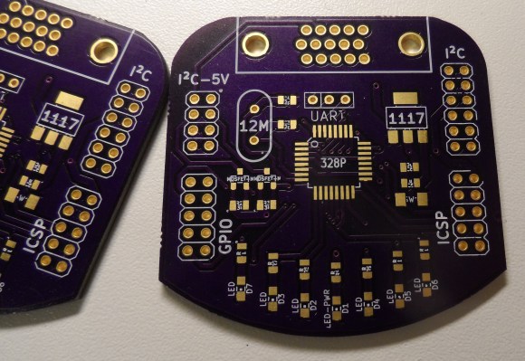
VGA, DVI, and HDMI ports use Display Data Channel (DDC) to communicate with connected displays. This allows displays to be plug and play. However, DDC is based on I2C, which is used in all kinds of electronics. To take advantage of this I2C port on nearly every computer, [Josef] built a VGA to I2C breakout.

This breakout is based on an older article about building a $0.25 I2C adapter. This adapter hijacks specific lines from the video port, and convinces the kernel it’s a standard I2C device. Once this is done, applications such as i2c-tools can be used to interact with the port.

[Josef] decided to go for overkill with this project. By putting an ATmega328 on the board, control for GPIOs and LEDs could be added. Level shifters for I2C were added so it can be used with lower voltage devices. The end product is an I2C adapter, GPIOs, and LEDs that can be controlled directly from the Linux kernel through an unused video port.

Counterfeit Apple Charger

More Counterfeit Apple Chargers Than You Can Shake An IPod At

Phones, MP3 players, designer bags, artwork, money…. anything with value will bring out the counterfeiters looking to make a quick buck. Sometimes the product being counterfeited isn’t even necessarily expensive. For example, an Apple iPad Charger. [Ken Shirriff] got a hold of a counterfeit iPad Charger, took it apart, and did some testing.

So why would someone buy a counterfeit product? To save some money! The counterfeits are usually cheaper to reel the potential buyer in thinking they are getting a deal. In this case, the Apple product costs $19 and the knock-off is $3, that’s a huge difference.

Continue reading “More Counterfeit Apple Chargers Than You Can Shake An IPod At”

Xbox One Headset 2.5 Mm Plug Adapter

In all of Microsoft’s grand wisdom they found it necessary to make the new Xbox One headset adapter without a standard 2.5 mm headset jack. People have invested great amounts of money in quality headsets for previous game platforms that now cannot jack into the Xbox One controllers. This may seem like a déjà vu hack from a week ago but it is different and adds more solutions for the annoying Xbox One headset compatibility problem.

[Jon Senkiw] A.K.A [Xandrel] wasn’t having any of this Microsoft nonsense so he cracked open the headset adapter case that plugs into the Xbox One controller. He photographed the PCB and wiring and realized he could fit a 2.5 mm headset jack from an old donor cellphone into the case. A dap of hot glue, some AWG 30 jumper wires and a bit of plastic trimming was all it took to get a jack inside the headset adapter just the way Microsoft should have done from the factory.

Previously when [octanechicken] added a 2.5 mm female phone adapter at the end of the cable he did not connect the black wire to anything being it was the 2nd side of a push-pull speaker. However, from looking at [Jon’s] photos he connected the speaker output wire to a solder pad on the PCB where the black wire originally connected, marked HPL, and he had nothing connected to the HPR pad. This seemed to work for [Jon] just fine, but is the opposite of what [octanechicken] did last week when he connected the blue wire to the speaker output which would have traced back to the HPR pad on the PCB.

This hack makes these controllers backwards compatible without too much issue being reported. If you have issues please report here or on [Jon’s] SE7ENSINS thread. He has also made comments on the thread that he is willing to help mod headsets, so if you’re not able to hack this yourself [Jon] might be willing to help.