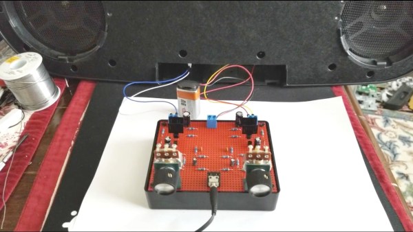
Vintage eight transistor stereo amplifier

Eight Transistor Stereo Amplifier From The Days Of Yore

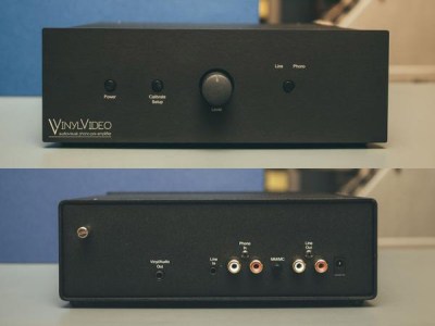
Reading an article about the first transistorized Hi-Fi amplifier, [Netzener] got the itch to make one. But what to use for the starting point? Enter an old Radio Shack P-Box stereo amplifier kit. After a few modernizations and tweaks, the result is an 8-transistor stereo amplifier that’s aesthetically pleasing, sounds great, and is fully documented.

The Radio Shack kit used germanium transistors, but with their high leakage current and low thermal conductivity, he decided to convert it to work with silicon transistors. He also made some improvements to the push-pull bias circuit and limited the high-frequency response. As for the finished product, in true [Netzener] style, he assembled it all to look like the original completed Radio Shack amplifier. He even wrote up a manual which you’d think, as we did at first, was the original one, giving that old, comfortable feeling of reading quality Radio Shack documentation.

Check out the video below where he uses a 9 V battery and half a watt per channel to fill a room with clear, stereo sound.

This isn’t the first Radio Shack kit that [Netzener] has adapted. Check out his single tube radio and classic neon “Goofy Light” box.

Continue reading “Eight Transistor Stereo Amplifier From The Days Of Yore”

A Unique Microphone Preamp

We live in a world in which nearly any kind of gadget or tool you can imagine is just a few clicks away. In many respects, this has helped fuel the maker culture over the last decade or so; now that people aren’t limited to the hardware that’s available locally, they’re able to create bigger and better things than ever before. But it can also have a detrimental effect. One has to question, for instance, why they should go through the trouble of building something themselves when they could buy it, often for less than the cost of the individual components.

The critic could argue that many of the projects that grace the pages of Hackaday could be supplanted with commercially available counterparts. We don’t deny it. But the difference between buying a turn-key product and building an alternative yourself is that you can make it exactly how you want it. That is precisely why [Sam Izdat] created this truly one of a kind microphone preamplifier. Could he have bought one online for cheaper? Probably. Could he have saved himself an immense amount of time and effort? Undoubtedly. Do we care? Not in the slightest.

The amplifier is based on the Texas Instruments INA217 chip, with an Arduino Nano and 128×64 OLED display providing the visualization. [Sam] was able to find a bare PCB for a typical INA217 implementation on eBay for a few bucks (see what we mean?), which helped get him started and allowed him to spend more time on the software side of things. His visualization code offers a number of interesting display modes, uses Fast Hartley Transforms, and very nearly maxes out the Arduino.

But perhaps no element of this build is as unique as the case. The rationale behind the design is that [Sam] wanted to compartmentalize each section of the device (power supply, amplifier, visualization) to avoid any interference. The cylindrical shapes were an issue of practicality: the compartments were constructed by using a hole saw to make wooden discs, which were then glued together and hollowed out. The case was stained and coated with polyurethane, but due to some slightly overzealous use of glue and fillers, the coloring isn’t uniform. This gives the final piece a somewhat weathered look, in sharp contrast to the decidedly high-tech looking display.

Overall, this build reminds us of the modular 3D printed amplifier we saw earlier in the year combined with these speaker-integrated Arduino VU meters.

Continue reading “A Unique Microphone Preamp”

Hybrid Lab Power Supply From Broken Audio Amp

The lab power supply is an essential part of any respectable electronics workbench. However, the cost of buying a unit that has all the features required can be eye-wateringly high for such a seemingly simple device. [The Post Apocalyptic Inventor] has showed us how to build a quality bench power supply from the guts of an old audio amplifier.

We’ve covered our fair share of DIY power supplies here at Hackaday, and despite this one being a year old, it goes the extra mile for a number of reasons. Firstly, many of the expensive and key components are salvaged from a faulty audio amp: the transformer, large heatsink and chassis, as well as miscellaneous capacitors, pots, power resistors and relays. Secondly, this power supply is a hybrid. As well as two outputs from off-the-shelf buck and boost converters, there is also a linear supply. The efficiency of the switching supplies is great for general purpose work, but having a low-ripple linear output on tap for testing RF and audio projects is really handy.

The addition of the linear regulator is covered in a second video, and it’s impressively technically comprehensive. [TPAI] does a great job of explaining the function of all the parts which comprise his linear supply, and builds it up manually from discrete components. To monitor the voltage and current on the front panel, two vintage dial voltmeters are used, after one is converted to an ammeter. It’s these small auxiliary hacks which make this project stand out – another example is the rewiring of the transformer secondary and bridge rectifier to obtain a 38V rail rated for twice the original current.

The Chinese DC-DC switching converters at the heart of this build are pretty popular these days, in fact we’re even seeing open source firmware being developed for them. If you want to find out more about how they operate on a basic level, here’s how a buck converter works, and also the science behind boost converters.

Continue reading “Hybrid Lab Power Supply From Broken Audio Amp”

A Guide To Audio Amps For Radio Builders

For hams who build their own radios, mastering the black art of radio frequency electronics is a necessary first step to getting on the air. But if voice transmissions are a goal, some level of mastery of the audio frequency side of the equation is needed as well. If your signal is clipped and distorted, the ham on the other side will have trouble hearing you, and if your receive audio is poor, good luck digging a weak signal out of the weeds.

Hams often give short shrift to the audio in their homebrew transceivers, and [Vasily Ivanenko] wants to change that with this comprehensive guide to audio amplifiers for the ham. He knows whereof he speaks; one of his other hobbies is jazz guitar and amplifiers, and it really shows in the variety of amps he discusses and the theory behind them. He describes a number of amps that perform well and are easy to build. Most of them are based on discrete transistors — many, many transistors — but he does provide some op amp designs and even a design for the venerable LM386, which he generally decries as the easy way out unless it’s optimized. He also goes into a great deal of detail on building AF oscillators and good filters with low harmonics for testing amps. We especially like the tip about using the FFT function of an oscilloscope and a signal generator to estimate total harmonic distortion.

The whole article is really worth a read, and applying some of these tips will help everyone do a better job designing audio amps, not just the hams. And if building amps from discrete transistors has you baffled, start with the basics: [Jenny]’s excellent Biasing That Transistor series.

[via Dangerous Prototypes]

Vintage Organ Donates Parts For Two New Instruments

It’s often hard to know what to do with a classic bit of electronics that’s taking up far too much of the living room for its own good. But when the thing in question is an electronic organ from the 1970s, the answer couldn’t be clearer: dissect it for its good parts and create two new instruments with them.

Judging by [Charlie Williams]’ blog posts on his Viscount Project, he’s been at this since at least 2014. The offending organ, from which the project gets its name, is a Viscount Bahia from the 1970s that had seen better days, apparently none of which included a good dusting. With careful disassembly and documentation, [Charlie] took the organ to bits. The first instrument to come from this was based on the foot pedals. A Teensy and a custom wood case turned it into a custom MIDI controller; hear it in action below. The beats controller from the organ’s keyboard was used for the second instrument. This one appears far more complex, not only for the beautiful, hand-held wooden case he built for it, but because he reused most of the original circuitry. A modern tube amp was added to produce a little distortion and stereo output from the original mono source, with the tip of the tube just peeking above the surface of the instrument. We wish there were a demo video of this one, but we’ll settle for gazing at the craftsmanship.

In a strange bit of timing, [Elliot Williams] (no relation, we assume) just posted an Ask Hackaday piece looking for help with a replacement top-octave generator for another 1970s organ. It’s got a good description of how these organs worked, if you’re in the mood to learn a little more.

Continue reading “Vintage Organ Donates Parts For Two New Instruments”

Biasing That Transistor: The Emitter Follower

We were musing upon the relative paucity of education with respect to the fundamentals of electronic circuitry with discrete semiconductors, so we thought we’d do something about it. So far we’ve taken a look at the basics of transistor biasing through the common emitter amplifier, then introduced a less common configuration, the common base amplifier. There is a third transistor amplifier configuration, as you might expect for a device that has three terminals: the so-called Common Collector amplifier. You might also know this configuration as the Emitter Follower. It’s called a “follower” because it tracks the input voltage, offering increased current capability and significantly lower output impedance.

The emitter follower circuit

Just as the common emitter amplifier and common base amplifier each tied those respective transistor terminals to a fixed potential and used the other two terminals as amplifier input and output, so does the common collector circuit. The base forms the input and its bias circuit is identical to that of the common emitter amplifier, but the rest of the circuit differs in that the collector is tied to the positive rail, the emitter forms the output, and there is a load resistor to ground in the emitter circuit.

As with both of the other configurations, the bias is set such that the transistor is turned on and passing a constant current that keeps it in its region of an almost linear relationship between small base current changes and larger collector current changes. With variation of the incoming signal and thus the  base current there is a corresponding change in the collector current dictated by the transistor’s gain, and thus an output voltage is generated across the emitter resistor. Unlike the common emitter amplifier this voltage increases or decreases in step with the input voltage, so the emitter follower is not an inverting amplifier.

Continue reading “Biasing That Transistor: The Emitter Follower”

Biasing That Transistor: The Common Base Amplifier

We’ve previously remarked upon a generation lucky enough to be well-versed in microcontrollers and computersised electronics through being brought up on the Arduino or the Raspberry Pi but unlucky enough to have missed out on basic electronics such as how to bias a transistor, and to address that gap we’ve taken a look at the basics of transistor biasing.

All the circuits we worked with in the previous article had the transistor’s emitter taken to ground, took their input from the base, and their output from the collector. This configuration, called a Common Emitter amplifier is probably the most common, but it is far from the only way to use a transistor. Once you have set up the bias voltage as we described to the point at which the transistor is in its linear region, there are several other ways in which the device can be used as an amplifier. The subject of this article is one of these configurations, so described because it takes the transistor’s base to the ground instead of the emitter, as a Common Base amplifier. Continue reading “Biasing That Transistor: The Common Base Amplifier”