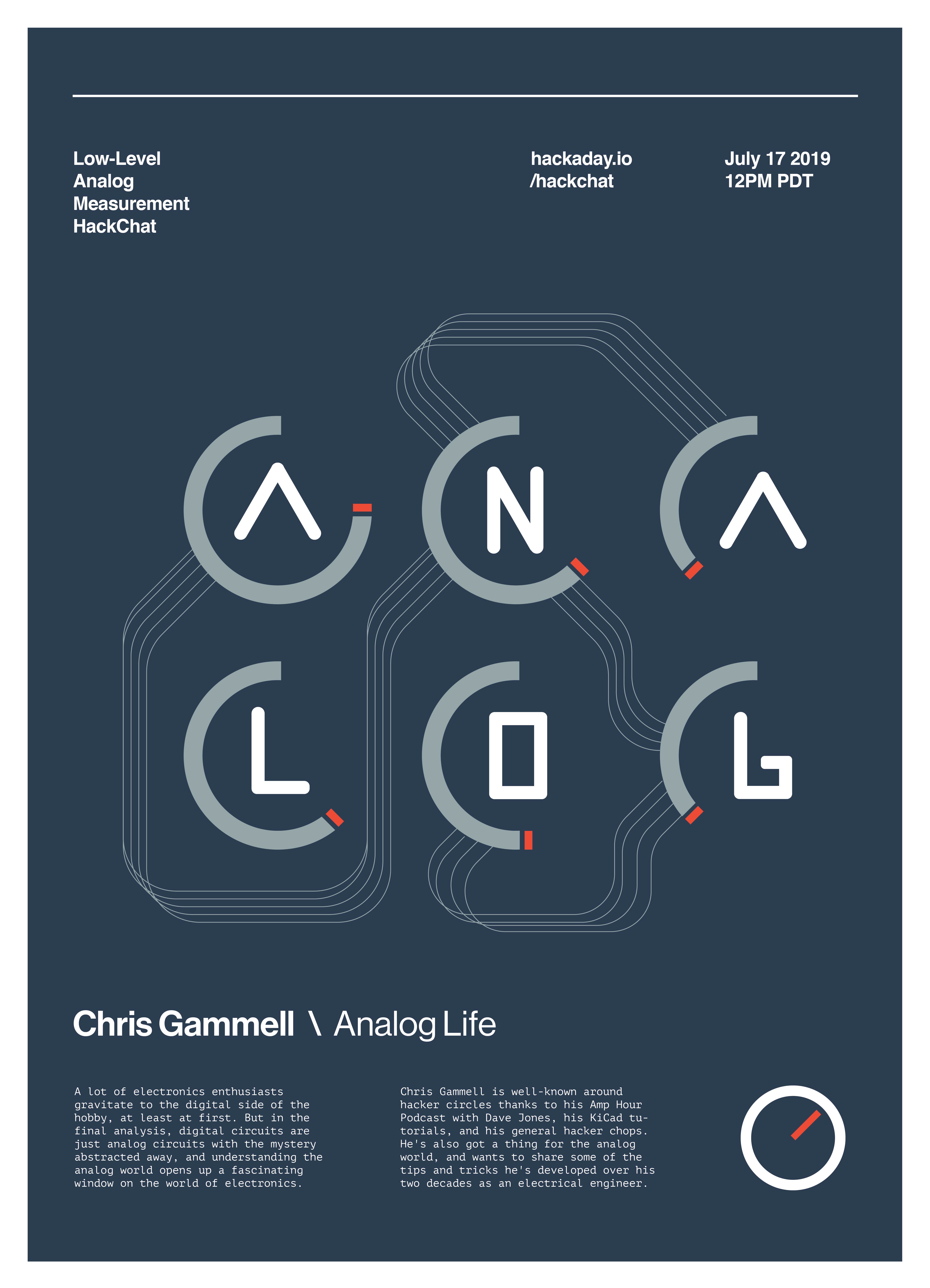
Electromagnet-Powered Pendulum

We’re always happy to see hackers inspired to try something different by what they see on Hackaday. To [SimpleTronic] has a project that will let you stretch your analog electronics skills in a really fun way. It’s an electromagnet pendulum analog circuit. Whether you’re building it, or just studying the schematics, this is a fun way to brush up on the non-digital side of the craft.

The pendulum is a neodymium magnet on the head of a bolt, dangling on a one foot aluminium chain. Below, a Hall Effect sensor rests atop an electromagnet — 1″ in diameter, with 6/8″ wire coiled around another bolt. As the pendulum’s magnet accelerates towards the electromagnet’s core, the Hall effect sensor registers an increase in voltage. The voltage peaks as the pendulum passes overhead, and as soon as the Hall Effect sensor detects the drop in voltage, the electromagnet flicks on for a moment to propel the pendulum away. This circuit has a very low power consumption, as the electromagnet is only on for about 20ms!

The other major components are a LM358N op-amp, a CD4001B quad CMOS NOR gate, and IRFD-120 MOSFET. [SimpleTronic] even took the time to highlight each part of the schematic in order to work through a complete explanation.

Continue reading “Electromagnet-Powered Pendulum”

Control Thy LED

In a previous article, I discussed LEDs in general and their properties. In this write-up, I want to give some examples of driving LEDs and comparing a few of the most commonly used methods. There is no “one size fits all” but I will try and generalize as much as possible. The idea is to be able to effectively control the brightness of the LED and prolong their life while doing it. An efficient driver can make all the difference if you plan to deploy them for the long-haul. Let’s take a look at the problem and then discuss the solutions. Continue reading “Control Thy LED”

Convert Temperatures The Analog Way

Everyone knows how to convert from Celsius to Fahrenheit, right? On a digital thermometer you just flick the little switch, on a weather app you change the settings, or if worse comes to worse, you let Google do the math for you. But what if you want to solve the problem the old-fashioned way? Then you pull out a few op amps and do your conversions analog style.

We’ve seen before how simple op amp circuits can do basic math, and the equation that [Kerry Wong] wants to solve is even simpler. Recalling the old T= 9/5·Tc + 32 formula (and putting aside the relative merits of metric versus traditional units; we’ve had enough of that argument already), [Kerry] walks us through a simple dual op amp circuit to convert the 1 mV/°C output of a thermocouple module to 1 mV/°F. The scaling is taken care of by a non-inverting amplifier with resistors chosen to provide a gain of 1.8, while the offset is handled by a differential amplifier that adds 32 mV to the scaled input. Strategically placed trimmers allow [Kerry] to tweak the circuit to give just the right conversion.

For jobs like this, it’s tempting to just use an analog input on an Arduino and take care of conversions in code. But it’s nice to know how to do it old school, too, and hats off to [Kerry] for showing us the details.

Continue reading “Convert Temperatures The Analog Way”

Bessel Filter Design

Once you fall deep enough into the rabbit hole of any project, specific information starts getting harder and harder to find. At some point, trusting experts becomes necessary, even if that information is hard to find, obtuse, or incomplete. [turingbirds] was having this problem with Bessel filters, namely that all of the information about them was scattered around the web and in textbooks. For anyone else who is having trouble with these particular filters, or simply wants to learn more about them, [turingbirds] has put together a guide with all of the information he has about them.

For those who don’t design audio circuits full-time, a Bessel filter is a linear, passive bandpass filter that preserves waveshapes of signals that are within the range of the filter’s pass bands, rather than distorting them in some way. [turingbirds]’s guide goes into the foundations of where the filter coefficients come from, instead of blindly using lookup tables like he had been doing.

For anyone else who uses these filters often, this design guide looks to be a helpful tool. Of course, if you’re new to the world of electronic filters there’s no reason to be afraid of them. You can even get started with everyone’s favorite: an Arduino.

Line Follower Has Lots Of Recycled Parts, But Zero Brains

Line Followers are a tried-and-true type of robot; both hardware and software need to be doing their job in harmony in order to be successful at a clearly defined physical task. But robots don’t always have microcontrollers and software, as [Mati_DIY]’s zero programming analog line follower demonstrates.

For readers used to seeing a Raspberry Pi or Arduino in almost everything, an analog robot whose “programming” exists only as a harmony between its discrete parts can be an eye-opener as well as an accessible project. A video of the robot in action is embedded below.

[Mati_DIY]’s design uses two CNY70 reflective sensors (which are essentially infrared emitter/phototransistor pairs) and an LM358 dual op-amp. Together, the sensors act as two near-sighted eyes. By using the output of each sensor to drive a motor via a transistor, the presence or absence of the black line is directly and immediately reflected by the motion of the attached motor. The more black the sensor sees, the more the motor turns. Electrically, that’s all that happens; but by attaching the right sensor to the left motor and the left sensor to the right motor, you get a robot that always tries to keep the black line centered under the sensors. Playing with the spacing of the motors and sensors further tweaks the performance.

Continue reading “Line Follower Has Lots Of Recycled Parts, But Zero Brains”

Don’t Fear The Filter: Lowpass Edition

There comes a time in every electronic designer’s life when, whether they know it or not, they need an analog filter in their design. If you’re coming from a digital background, where everything is nice and numeric, the harsh reality of continuous voltages can be a bit of a shock. But if you’re taking input from, or sending output to the big analog world out there, it pays to at least think about the frequency-domain properties of the signal, and maybe even do something about them.

Designing an analog filter to fit your needs can be a bit of a daunting task: there are many factors that you’re going to need to consider, and they all interact. It’s easy to get lost. We’re going to simplify this as much as possible by instead focusing on a few common applications and building up the simplest possible filters that work well for them.

Today, we’re going to consider the lowpass filter, and specifically a Sallen-Key filter with Butterworth characteristics and a second-order rolloff. Sound like word salad? We’ll fix that up right away, because this is probably the single most important filter to have in your analog toolbox for two very common use cases: pulse-width modulated (PWM) output and analog-to-digital conversion (ADC) input.

Continue reading “Don’t Fear The Filter: Lowpass Edition”

Filtering Noisy Data With An Arduino

One of the first frustrating situations a beginning microcontroller programmer will come across is the issue of debouncing switches. Microcontrollers are faster than switches, and the switch has yet to be built that can change state in zero time like they can on paper. This hurdle is easily overcome, but soon we are all faced with another issue: filtering noise from an analog signal. Luckily [Paul Martinsen] has put together a primer of three different ways to use an Arduino to filter signals.

The first (and fastest, simplest, etc.) way to filter an analog signal is to sample a bunch of times and then average all of the samples together. This will eliminate most outliers and chatter without losing much of the information. From there, the tutorial moves on to programming a running average to help increase the sample time (but consume much more memory). Finally, [Paul] takes a look at exponential filters, which are recursive, use less memory, and can be tweaked to respond to changes in different ways.

[Paul] discusses all of the perks and downsides of each method and provides examples for each as well. It’s worth checking out, whether you’re a seasoned veteran who might glean some nuance or you’re a beginner who hasn’t even encountered this problem yet. And if you’re still working on debouncing a digital input, we have you covered there, too.