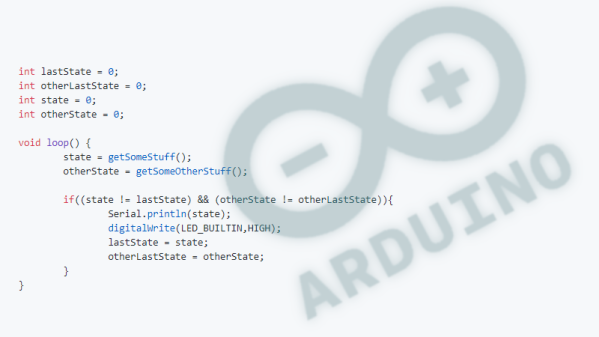
The readability of your code can make the difference between your project being a joy to work on, or an absolute headache. This goes double when collaborating with others. Having easily parsed code reduces your cognitive load and makes solving problems easier. To try and help with this, [PTS93] developed the Stator library to make certain common tasks simpler to read.
The aim of the library is to get rid of piles of state tracking variables and endless if/else statements – hence the name. It’s designed primarily for the Arduino IDE but doesn’t have any dependencies on the API, so can be used in other C++ environments. It comes with a variety of neat tools for common jobs, such as reading an analog sensor with hysteresis around a trigger point, as well as easy ways to track state changes across multiple variables. By using basic English terms instead of condition checks and mathematical operators, it can make things more readable and easier to follow.
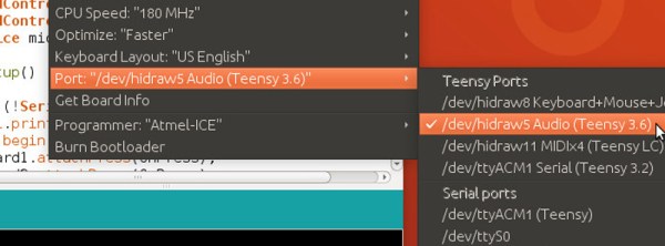
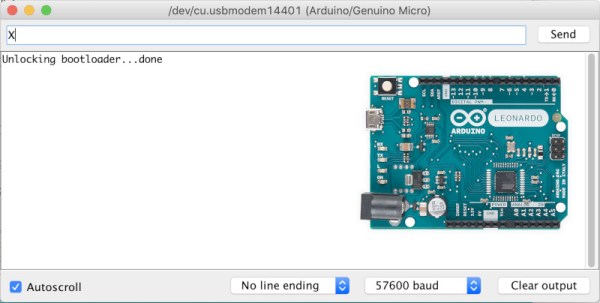
The power of the Arduino platform has always been in its easy to use libraries that make everything easier, from interfacing LCDs to working with Amazon Dash buttons.


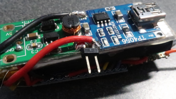
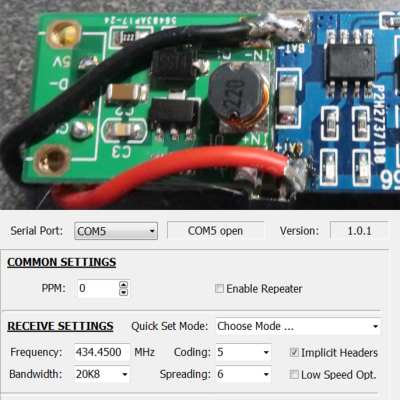 [Dave Akerman]’s interest in high-altitude projects means he is no stranger to long-range wireless communications, for which LoRa is amazingly useful. LoRa is a method of transmitting at relatively low data rates with low power over long distances.