The mechanical keyboard community is a vibrant, if not fanatical, group of enthusiasts determined to find as many possible ways of assembling, building, and using as many high-quality keyboards as possible. With so many dedicated participants, most things that can be done with a keyboard already have been done. So when something as unique as this split keyboard that also doubles as a mouse pops up, we take notice.
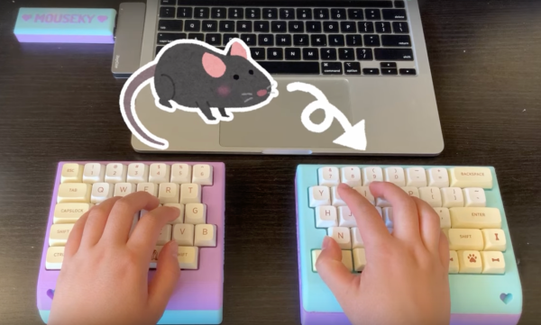
The keyboard is a custom build from [Taliyah Huang] which uses a pair of Arduinos, one in each half of the keyboard, to communicate key and mouse information to a third Arduino which is plugged in to her laptop. The right-hand half of the keyboard also includes the circuitry from an optical mouse, which gets powered up when the caps lock button is held down. When activated, this allows the keyboard to be used as a mouse directly. It also includes support for most Mac gestures as well, making it just as useful as a trackpad.
While there were some problems with the design, including being slightly too tall to be ergonomic and taking nearly 24 hours of soldering to complete, the prototype device is an interesting one especially since it allows for full control of a computer without needing a dedicated mouse. For other unique mechanical keyboard concepts, we recently featured this build which takes design and functionality cues from the Commodore 64.