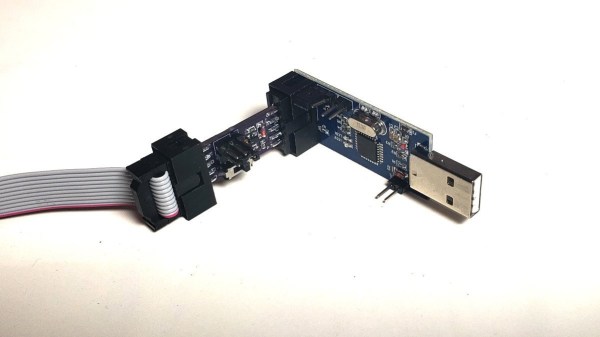
A HVTPI adapter plugged into a USBASP, with a an IDC10 cable plugged into it in turn

HVTPI Primer And Toolkit Equips You For BOM Substitutions

Novel programming interfaces for MCUs might catch us by surprise, but then we inevitably get up to speed with the changes required. Today’s bastion is HVTPI – a “12V reset” addition to the TPI we’ve just started getting used to, and [Sam Ettinger] has shared a simple circuit to teach us all about it, along with PCB files and detailed explanations of how it all works.

HVTPI is an add-on on top of TPI, for which, as Sam explains, you need to hold RST at 12V when TPI would have it be low logic level, and leave it at Vtarget otherwise. For that, he has designed a variety of interposer boards of various complexity and requirements; explaining the choices behind each one and clearing up any misunderstandings that might occur on your way. All of the board files (and the TPI write-up copy) are caringly shared with us in a git repository, too! As a result, if you have an USB-ASP or an Arduino available, now you also have everything to do HVTPI, thanks to Sam’s work and explanations.

We’ve been covering Sam’s exploits before, and can’t help but be grateful for the stop-and-explain detour along the way. HVTPI being used on very small ATTiny parts, we wonder if something new in the vein of his recent FPC board able to fit and function entirely within a Type-C cable end!

With chip shortages, investigating programming interfaces for small and obscure yet in-stock microcontrollers has been, quite literally, paying off, and if you got some projects that need a MCU but won’t consume a whole lot of resources, it could be time to give an ATTiny10 a go. What’s the worst that can happen – you make the smallest chiptunes ever?
I2C To The Max With ATtiny

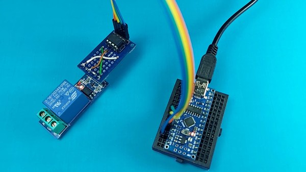
The Arduino is a powerful platform for interfacing with the real world, but it isn’t without limits. One of those hard limits, even for the Arduino MEGA, is a finite number of pins that the microcontroller can use to interface with the real world. If you’re looking to extend the platform’s reach in one of your own projects, though, there are a couple of options available. This project from [Bill] shows us one of those options by using the ATtiny85 to offload some of an Arduino’s tasks using I2C.

I2C has been around since the early 80s as a way for microcontrollers to communicate with each other using a minimum of hardware. All that is needed is to connect the I2C pins of the microcontrollers and provide each with power. This project uses an Arduino as the controller and an arbitrary number of smaller ATtiny85 microcontrollers as targets. Communicating with the smaller device allows the Arduino to focus on more processor-intensive tasks while giving the simpler tasks to the ATtiny. It also greatly simplifies wiring for projects that may be distributed across a distance. [Bill] also standardizes the build with a custom development board for the ATtiny that can also double as a shield for the Arduino, allowing him to easily expand and modify his projects without too much extra soldering.

Using I2C might not be the most novel of innovations, but making it easy to use is certainly a valuable tool to add to the toolbox when limited on GPIO or by other physical constraints. To that end, [Bill] also includes code for an example project that simplifies the setup of one of these devices on the software end as well. If you’re looking for some examples for what to do with I2C, take a look at this thermometer that communicates with I2C or this project which uses multiple sensors daisy-chained together.

Continue reading “I2C To The Max With ATtiny”

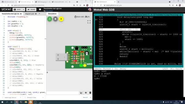
Screenshot of debugging the Wokwi Arduino simulator

Digging Into An ATtiny Simulator Bug With GDB

Being able to track down a bug in a mountain of source code is a skill in its own right, and it’s a hard skill to learn from a book or online tutorial. Besides the trial-by-fire of learning while debugging your own project, the next best thing is to observe someone else’s process. [Uri Shaked] has given us a great opportunity to brush up on our debugging skills, as he demonstrates how to track down and squish a bug in the Wokwi Arduino simulator.

A user was kind enough to report the bug and include the offending Arduino sketch. [Uri]’s first step was to reduce the sketch to the smallest possible program that would still produce the bug.

Once a minimal program had been produced, it was time to check whether the problem was in one of the Arduino libraries or in the Wokwi simulator. [Uri] compiled the sketch, loaded it onto a ATtiny85, and compared the behavior of the simulator and the real thing. It turns out the code ran just fine on a physical ATtiny, so the problem must have been in the Arduino simulator itself.

To track down the bug in the simulator, [Uri] decided to break out the big gun—GDB. What follows is an excellent demonstration of how to use GDB to isolate a problem by examining the source code and using breakpoints and print statements. In the end, [Uri] managed to isolate the problem to a mis-placed bit in the simulation of the timer/counter interrupt flag register.

If you’d like to see more of [Uri]’s debugging prowess, check out his dive into an ATtiny’s write protection and configuration fuses. If you’ve been wowed by the power of GDB and want to learn more, check out this quick tutorial!

Continue reading “Digging Into An ATtiny Simulator Bug With GDB”

mRNA badge next to an image of the actual Moderna vaccine nanoparticle.

Celebrate MRNA Vaccine With This Badge That Blinks The Nucleotide Code

To celebrate getting his second vaccine dose [Paul Klinger] combined two of our favorite things — blinking lights and wearable tech — to create an awesome mRNA vaccine badge.

The badge, which is designed to be worn like a pendant, will slowly blink through all 4,000 nucleotides of the Moderna vaccine over the course of 10 minutes. Watch the video after the break to see it in action. Don’t worry if you got the Pfizer vaccine, you can use the interface button on the back of the badge to change over to Pfizer’s mRNA sequence instead. There’s even a handy legend on the badge, identifying the lipids in case your microbiology skills are a bit rusty.

On the reverse side of the board, you will find a handful of current limiting resistors, a CR2032 battery holder, and the ATtiny1617 microcontroller that runs everything. To assist in converting the mRNA sequence into LED pulses, [Paul] wrote a Python script that will automatically import the nucleotide string from the standard .fasta file and store each nucleotide in just 2 bits, allowing the entire sequence to fit in the program memory of the microcontroller.

This isn’t [Paul’s] first RNA-related project; he originally developed the aforementioned Python script to compress the entirety of the COVID-19 sequence, containing over 30,000 nucleotides, into program memory for his Virus Blinky project, that we featured last year.

Continue reading “Celebrate MRNA Vaccine With This Badge That Blinks The Nucleotide Code”

A Perfect Clock For Any Hacker’s Ohm

The vast majority of us are satisfied with a standard, base ten display for representing time. Fewer of us like to be a bit old-fashioned and use a dial with a couple of hands that indicate the time, modulo twelve. And an even smaller minority, with a true love for the esoteric, are a fan of binary readouts. Well, there’s a new time-telling game in town, and as far as we’re concerned it’s one of the best ones yet: resistor color codes.

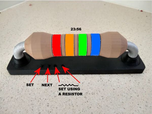
The Ohm Clock is, as you may have guessed, a giant model of a resistor that uses its color bands to represent time.  Each of the four bands represents a digit in the standard HH:MM representation of time, and for anybody well-versed in resistor codes this is sure to be a breeze to read. The clock itself was designed by [John Bradnam]. It’s body is 3D printed, with RGB LEDs to brightly illuminate each segment. The whole thing is controlled by an old favorite – an ATtiny, supported by a Real Time Clock (RTC) chip for accurate timekeeping.

You can set the time in the traditional fashion using buttons, or — and here’s the brilliant part — you can use a resistor. Yup, that’s right. Connecting a 220 Ohm resistor across two terminals on the clock will set the time to 2:20. Genius.

When you come across an art as old as timekeeping, it’s easy to assume that everything’s already been done. We have sundials, hourglasses, analog clocks, digital watches, those cool clocks that use words instead of numbers, the list goes on. That’s why it’s so exciting to see a new (and fun!) idea like this one emerge.

How Tiny Can A Microcontroller Dev Board Be!

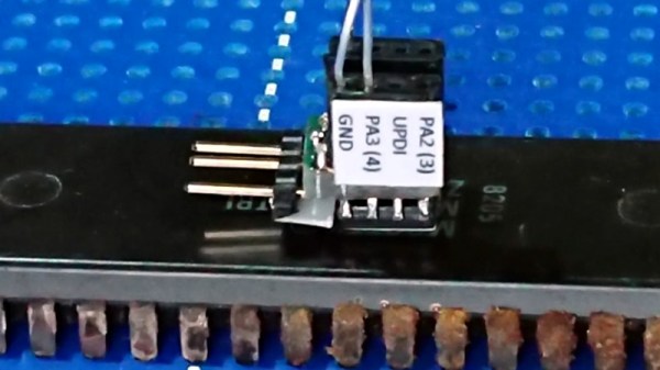
With innumerable microcontroller boards on the market it’s sure that there will be one for every conceivable application or user. Among them are some seriously tiny ones, but this wasn’t enough for [Alun Morris]. Wanting to see how small he could make an ATtiny board without a custom PCB, he took a SOIC-8 version of the popular minimalist processor and mated it to a 6mm by 8mm piece of 0.05″ prototyping board to create a device that is dwarfed by its connectors.

It’s an extremely simple circuit and hardly something that hasn’t been done before, but the value here is in the tricky soldering to make it rather than its novelty. The ATtiny402 and three passive SMD components are fitted on the smallest possible sliver of prototyping board to contain them, and the female headers and set of programming pins contribute far more to the volume of the device than the board itself. He also tried a side-on design with two smaller slivers of board before settling on the more conventional layout. The demonstration of the system in action seen in the video below the break is a magnetic flux detector, dwarfed by the 40-pin DIP Z80 it is sitting on.

A lot of boards claim to be tiny, but few are this small. This ESP32 is a more usual contender.

Continue reading “How Tiny Can A Microcontroller Dev Board Be!”

Old Gas Meter Gets Smart With The ESP8266

Measuring the usage of domestic utilities such as water, gas or electricity usually boils down to measuring a repetitive pulse signal with respect to time. To make things easy, most modern utility meters have a pulsed LED output, which can be used to monitor the consumption by using an external optical sensor. But what do you do if your meter isn’t so cooperative?

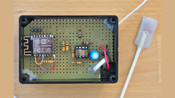
That’s exactly what [Francesco] had to figure out while developing the non-invasive gas tracking system he calls ESPmeter. His meter might not have an LED, but it did have a magnet attached to the counter disk which activated an internal hall sensor. With some hacking, he was able to attach an external Hall-effect sensor to pick up this magnet and use the signal to monitor his daily gas consumption.


A big stumbling block in such projects is the issue of powering the device for an extended period, and remembering when it’s time to change the batteries. With the clever use of commonly available parts, he was able to reduce power consumption allowing three AA batteries to last about a year between changes. For one thing, he uses an ATtiny13 to actually read the sensor values. The chip doesn’t run continuously, its watchdog is set at 1 Hz, ensuring that the device is woken up often enough so that it has time to power up the sensor and detect the presence of the magnet. Battery voltage is also measured via a voltage divider connected to the chip’s ADC pin.

At regular intervals throughout the day, the ESP8266 polls the ATtiny13 to pull the stored sensor pulses and voltage measurement. Then at midnight, the ESP transmits all the collected data to a remote server. Overall, this whole scheme allows [Francesco] to reliably gather his gas consumption data while not having to worry about batteries until he gets the low voltage notification. Since the data visualization requirements are pretty basic, he is keeping things simple by using Plotly to display his time series data.

If you are unfortunate enough to have an even older meter which doesn’t use optical or magnetic rotation sensing, you can use a disassembled mouse to keep track of the Gas Meter.