[Pawel] himself notes that the device isn’t something the average person would necessarily need, but it does have its applications. There are times when working with various battery chemistries that it is desired to have them held at a certain state of charge. Also, such devices can be used to measure the capacity of batteries by timing how long they take to discharge when placed under a given load.
The build is one that takes advantage of the available parts of the modern hacker’s junkbox. An Arduino is used with an N-channel MOSFET to switch a resistive load. That load consists of load resistors designed for automotive use, to allow cars originally designed for filament bulbs to use LED indicator lights without the flash frequency speeding up. The resistors are 10 ohms and rated at 50 W, so they’re just about right for ganging up to discharge small LiPo batteries in a short period of time.
[Pawel] has tested the basic concept, and has things working. Next on the agenda is to find a way to get rid of the excess heat, as the current design has the resistors reaching temperatures of 158 °F (70 °C) in just a few minutes. Use some of that power to drive a fan?
You’d be forgiven for not realizing there’s still a diehard group of people out there carrying around dedicated MP3 players. While they were all the rage a decade or so back, most consumers have since moved over to using their handy dandy pocket supercomputer for playing their music. Plus controlling every other aspect of their personal life and finances, of course. Though that’s another story entirely.
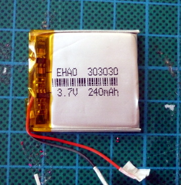
But as [Conno Brooks] explained to us, there’s a sizable group of open source fanatics who prefer to store their jams on devices running the Rockbox firmware. Only problem is, some of the desirable Rockbox-compatible players are from the Golden Age of dedicated players, and aren’t getting any younger. In a recent blog post, he briefly goes over his ultimately successful attempt to put a new-made battery into his Sansa Clip+, a particularly desirable player that was released in 2009.
There are a few problems with the procedure that has kept it from being very widespread, according to [Conno]. For one, the Sansa Clip+ is tiny and not easily disassembled without destroying it. Worse, the diminutive 30mm x 36mm x 3mm OEM battery is effectively unobtainium. But ironically he was able to find an even smaller battery which seemed like it should work, assuming he could get it wired up.
The OEM battery on the Clip+ uses three wires, which [Conno] presumed was part of some thermal protection system. He first tried to take the circuit board off the original dead battery and graft it onto the modern cell, but something must have tripped because the resulting Franken-pack didn’t output any voltage. On his second attempt he simply ignored the third wire, and luckily the Clip+ didn’t seem to complain and started up as expected.
[Conno] says there’s some careful flexing required to get the new pack installed and the Clip+ closed properly, and the device’s runtime is somewhat diminished by the new battery’s lower capacity. But if it means another few years of keeping Big Brother out of your digital media habits, he figures it’s a worthy trade.
Building your own weather station is a fun project in itself, but building it to be self-sufficient and off-grid adds another set of challenges to the mix. You’ll need a battery and a solar panel to power the station, which means adding at least a regulator and charge controller to your build. If the panel and battery are small, you’ll also need to make some power-saving tweaks to the code as well. (Google Translate from Italian) The tricks that [Danilo Larizza] uses in his build are useful for more than just weather stations though, they’ll be perfect for anyone trying to optimize their off-grid projects for battery and solar panel size.
When it comes to power conservation, the low-hanging fruit is plucked first. [Danilo] set the measurement intervals to as long as possible and put the microcontroller (a NodeMCU) to sleep in between. Removing the power from the sensors when the microcontroller was asleep was another easy step, but the device was still crashing overnight. Then he turned to a hardware solution and added a more efficient battery charger to the setup, which saved even more power. This is all the more impressive because the station communicates via WiFi which is notoriously difficult to run in low-power applications.
Besides the low power optimizations, the weather station itself is interesting for its relative simplicity. It could be built with things most of us have knocking around. Best of all, [Danilo] published the source code on his site, so most of the hard work has been done already. If you’re thinking he seems a little familiar, it’s because we’ve featured some of his projects before, like his cheap WiFi extender antenna and his homemade hybrid tube amplifier.
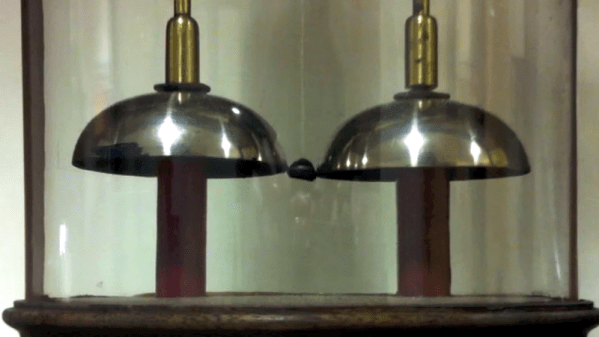
It is good advice to change batteries in your fire alarms at least once a year. Even our low-power LCD calculators need new batteries from time to time. But at the University of Oxford, they have an electric bell that has been ringing essentially non-stop on one set of batteries for about 178 years! Is the energy crisis solved then? Perhaps not. The bells require a high voltage but very little current and the pair of batteries — piles in the parlance of 1840 — have kept the charge flowing for about 10 billion rings. As you can see in the video below, though, the ringing isn’t very vigorous.
How does it work? When you think of converting electrical power to mechanical motion you probably think of a motor, even though there are plenty of other transducers like speakers, muscle wires, and solenoids. Arguably the first device was electrostatic bells that were invented by a Scot named [Andrew Gordon] around 1742. [Ben Franklin] made them famous, though, so they are often called Franklin bells.
Nearly a decade ago my friend [Dru] gave me an unforgettable tour late at night of Stokes Croft, the inner suburb of Bristol known at the time for its counterculture and artistic scene. It’s a place dominated by building-sized graffiti and murals, and it has a particular association with the Bristolian street artist [Banksy]. If you’ve not seen a Banksy in the wild, the place to do it is by Bristol Saturday night street lighting to the sound of passing revelers and traffic on the A38.
[Banksy] is famous aside from his anonymity, for his pranks upon the art world. The (real) elephant in the room or the Dismalland theme park are his stock in trade, and you may have seen another prank of his in the news in the last day. One of his paintings, the 2006 Girl With A Balloon sold at auction for over a million quid, and as the gavel fell a hidden shredder in the picture frame sprang into life and partially shredded the canvas. The report suggests that a number of [Banksy]’s associates were present at the event, and that one of them was detained with a device that might have been a remote control trigger for the shredder. The quote from Sotheby’s Europe head of Contemporary Art, [Alex Branczik] says it all: “We got Banksy’d”.
The interior of the Banksy shredder frame, taken from a frame of the video.
[Banksy]’s cool and all that, but where’s the hack? The artist briefly put up a video with a few details, but aside from showing us a row of craft knife blades and a tantalizing but fleeting glimpse of a few equipment enclosures, it’s short on technical details. We can see what appears to be at least one motor, and those white boxes may be batteries, but that’s it.
This hasn’t stopped some fevered speculation as to how the feat was achieved. A home-made shredder would require a significant amount of readily available power, and since this one has seemingly lain undetected within the frame since 2006, that power source needs to have possessed both exceptional energy density and retention. We can’t imagine many consumer grade batteries in 2018 being able to retain a charge for twelve years, so how on earth did he do it? Our best guess is that a primary battery was involved, as anyone who has found a neglected Duracell in a box of electronics from their youth will tell you it’s not unknown for decent quality alkaline cells to live well beyond their shelf lives, and other chemistries are specifically designed with that property in mind. Even so, for the cells to power a receiver circuit in standby for so long would certainly tax their capabilities, so it has also been suggested that a concealed switch could have been flipped by a [Banksy] accomplice during the viewing phase to activate the system. There are still so many unanswered questions that it’s certainly piqued our technical curiosity. Sadly we don’t know [Banksy] to ask him how he did it, but we welcome speculation both informed and otherwise in the comments.
Our own [Joe Kim]’s tribute to the work in question.Meanwhile the piece itself lies half shredded and protruding from the base of the frame. On the face of it that’s ruined the painting as an artwork, but of course this is a Banksy. Normal rules seem not to apply, so the notoriety it has received will no doubt mean that its shredded remains are an artwork in themselves, and possibly even one worth more.
Banksy owners worldwide are no doubt now paying a huge amount more attention to the artist’s frames than previously, but Hackaday readers need not worry. Our London Unconference logo and stickers featured a [Joe Kim] homage to the Banksy in question, which we can guarantee does not incorporate an artist’s shredder.
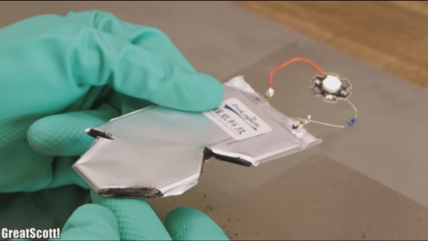
Affordable solid-state batteries large enough for cell phones and drones have been promised for a long time but seem to always be a few years away from production. In this case, Taiwan based Prologium sent [GreatScott] samples of their Lithium Ceramic batteries (LCBs) to test, and even though they’re not yet commercial products, who are we to refuse a peek at what they’ve been up to? They sent him two types, flexible ones (FLCBs) and higher capacity stiff ones (PLCBs).
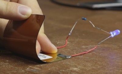
The FLCBs were rated at 100 mAh and just 2 C, both small values but still useful for wearables, especially given their flexibility. Doing some destructive testing, he managed to keep an LED lit while flexing the battery and cutting away at it with tin snips.
Switching to the thicker 7.31 Wh PLCB, he measured and weighed it to get an energy density of 258 Wh/L and a specific energy of 118 Wh/kg, only about 2/3rds and 1/2 that of his LiPo and lithium-ion batteries. Repeating the destructive tests with these ones, the LED turned off and smoke appeared while cutting and hammering a nail through, likely due to the shorts caused by the electrically conductive tin snips and nail. But once the snips and nail were moved away, the smoke stopped and the LED lit up again. Overcharging and short-circuiting the batteries both caused the solder connecting the wires to them to melt but nothing else happened. Rapidly discharging through a resistor only resulted in a gradual voltage drop. Clearly, these batteries are much safer than their LiPo and lithium ion counterparts. That safety and their flexibility seem to be their current main selling points should they become available for us hackers. Check out his tests in the video below.
Batteries placed in harm’s way need to be protected. A battery placed where a breakdown could endanger a life needs to be protected. Lithium-ion batteries on the bottoms of electric cars are subject to accidental damage and they are bathed in flame-retardant epoxy inside a metal sled. Phone batteries are hidden behind something that will shatter or snap before the battery suffers and warrant inspection. Hoverboard batteries are placed behind cheap plastic, and we have all seen how well that works. Batteries contain chemicals with a high density of energy, so the less exploding they do, the better.
Researchers at Oak Ridge National Laboratory have added a new ingredient to batteries that makes them armored but from the inside. The ingredient is silica spheres so fine it is safe to call it powder. The effect of this dust is that the electrolyte in every battery will harden like cornstarch/water then go right back to being a liquid. This non-Newtonian fluid works on the principal principle of shear-thickening which, in this case, says that the suspension will become harder as shear force is applied. So, batteries get rock hard when struck, then go back to being batteries when it is safe.
Non-Newtonian fluids are much fun, but we’re also happy to see them put to use. The same principle works in special speed bumps to allow safe drivers to continue driving but jolts speeders. Micromachines can swim in non-Newtonian fluids better than water in some cases.


![Our own [Joe Kim]'s tribute to the work in question.](https://hackaday.com/wp-content/uploads/2017/07/london.jpg)
 The FLCBs were rated at 100 mAh and just 2 C, both small values but still useful for wearables, especially given their flexibility. Doing some destructive testing, he managed to keep an LED lit while flexing the battery and cutting away at it with tin snips.