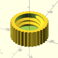
Remember learning to tie your shoes or ride a bike? Like many things, that’s easy once you know how to do it, but seems impossible before you learn. [NovaSpirit] asserts that Freecad is simple, and provides a simple walkthrough to create a part in the video below.
If this were riding a bike, this tutorial would be akin to watching someone ride a bike to pick up tips. You’d probably still want to have someone explain details to you before you attempt it yourself.
[Levi] whipped up his brushless DC motor design in OnShape. The motor has six coils in the stator, with the rotor carrying eight neodymium magnets. It’s an axial flux design, with the rotor’s magnets sitting above the coils. This makes construction very easy using 3D printed components. Axial flux motors also have benefits when it comes to power density and cooling, though optimization is outside the scope of [Levi]’s work here.
[Levi]’s video covers both the development of the motor itself as well as the drive circuit, too. The latter is of key value if you’re interested in the vagaries of driving these motors, which is far more complex than running a simple brushed motor. He even gets his motor up to 12,500 rpm with his homebrewed drive circuit.
Making your own motors can help you solve some difficult engineering challenges, like building motorized rollerblades. Alternatively, if winding coils sounds too slow and too hard, you can just use off-the-shelf gear and hack it to make it work. Here, we support both methods.
As much as we might all like it if manufacturers supported their products indefinitely with software updates or replacement parts, this just isn’t feasible. Companies fail or get traded, technologies evolve, and there’s also an economic argument against creating parts for things that are extremely old or weren’t popular in the first place. So, for something like restoring an old car, you might have to resort to fabricating replacement parts for your build on your own. [MangoJelly] shows us how to build our own replacement parts in FreeCAD in this series of videos.
The build does assume that the original drawings or specifications for the part are still available, but with those in hand FreeCAD is capable of importing them and then the model scaling to match the original specs shown. This video goes about recreating a hinge on an old truck, so with the drawings in hand the part is essentially traced out using the software, eventually expanding it into all three dimensions using all of the tools available in FreeCAD. One of the keys to FreeCAD is the various workbenches available that all have their own sets of tools, and being able to navigate between them is key to a build like this.
FreeCAD itself is an excellent tool for anyone repairing old vehicles like this or those making 3D prints, designing floorplans for houses, or really anything you might need to model in a computer before bringing the idea into reality. It does have a steep learning curve (not unlike other CAD software) so it helps to have a video series like this if you’re only just getting started or looking to further hone your design skills, but the fact that it’s free and open-source make it extremely attractive compared to its competitors.
When USB first came on the scene, one of the benefits was that essentially any four conductors could get you to the point where you could send information at 12 Mbps. Of course everything is faster these days, and reaching today’s speeds requires a little bit more fidelity in the cables. This simple tester makes sure that your modern cables are actually up to the task.
One of the design goals of this project is to automate away the task of testing cables or finding one that works, especially before thinking a problem with a device is somewhere in software, spending hours or days debugging, before realizing that it’s actually being caused by a hardware malfunction. The small PCB has two USB-C fittings to plug in both of the ends of a cable to, and between those connectors there is a number of LEDs. Each LED is paired to one the many conductors within the USB cable, and not only does it show continuity of these conductors but it can also show a high resistance connection via a dimly-lit or off-color display from an LED.
One of the other interesting facets of this build is the use of JITX, which is a software-defined electronics CAD tool which allows PCB design to be automated by writing out the requirements of the PCB into code, rather than drawing it manually. It’s worth a look, and a lot of the schematics of this particular project as well as some discussion on this software can be found on the project’s GitHub page. Incidentally, if this tester looks familiar, it’s probably because your’re thinking of the open source hardware USB tester created by [Álvaro Prieto].
Quick references are handy, but sometimes it’s nice to have a process demonstrated from beginning to end. In that spirit, [Darren Stone] created a video demonstrating how to model a twisted part in FreeCAD, showing the entire workflow of creating the part as a blend of surfaces and curves that get turned into a solid.
FreeCAD is organized using the concept of multiple “workbenches” which are each optimized for different tools and operations, and [Darren] walks through doing the same jobs in a few different ways.
This twisted bracket is a simple part that is nevertheless nontrivial from a CAD perspective, and that makes it a good candidate for showing off the different workbenches and tools.
The video below is also pretty good overall demonstration of what designing a part from a mechanical drawing looks like when done in FreeCAD. As for mechanical drawings themselves, we’ve seen FreeCAD can be used to make those, too.
There are very few legal ways of obtaining ROM files for video games, and Nintendo’s lawyers are extremely keen on at least reminding you of the fact that you need to own the game cart before obtaining the ROM. With cart in hand, though, most will grab a cart reader to download the game files. While this is a tried-and-true method, for GameBoy games this extra piece of hardware isn’t strictly required. [Travis Goodspeed] is here to show us a method of obtaining ROM files from photographs of the game itself.
Of course, the chips inside the game cart will need to be decapped in order to obtain the pictures, and the pictures will need to be of high quality in order to grab the information. [Travis] is more than capable of this task in his home lab, but some work is still required after this step.
The individual bits in the Game Boy cartridges are created by metal vias on the chip, which are extremely small, but still visible under a microscope. He also has a CAD program that he developed to take this visual information and extract the data from it, which creates a ROM file that’s just as good as any obtained with a cart reader.
This might end up being slightly more work especially if you have to decap the chips and take the photographs yourself, but it’s nonetheless a clever way of obtaining ROM files due to this quirk of Game Boy technology. Encoding data into physical hardware like this is also an excellent way of ensuring that it doesn’t degrade over time. Here are some other methods for long-term data storage.
The 3D printing revolution has transformed a lot of industries, but according to [Insider Business] the car industry still uses clay modeling to make life-sized replicas of new cars. The video below shows a fascinating glimpse of the process of taking foam and clay and making it look like a real car. Unlike the old days, they do use a milling machine to do some rough work on the model, but there’s still a surprising amount of manual work involved. Some of the older film clips in the video show how hard it was to do before the CNC machines.
The cost of these models isn’t cheap. They claim that some of the models have cost $650,000 to create. We assume most of that is in salaries. Some models take four years to complete and a ton of clay.