It’s no secret that Maker Faire is highly geared toward the younger crowd. This doen’t mean the Faire is completely devoid of the historic; the Bay Area Maker Faire is right in the heart of the beginnings of the computer industry, and a few of the booths are showing off exactly how far computers have come over the last forty years.
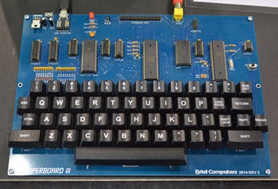 [Vince Briel] of Briel Computers has a booth showing off his wares, mostly modern reimaginings of vintage computers. His table is loaded up with replica 1s, a board that’s much smaller but still completely compatible with the Apple I. The MicroKIM made an appearance, but the crown jewel is [Vince]’s Superboard III, a replica of the Ohio Scientific Superboard II. It’s your basic 6502 computer with 32k of RAM, but unlike just about every other modern retrocomputer out there, [Vince] put the keyboard right on the main board.
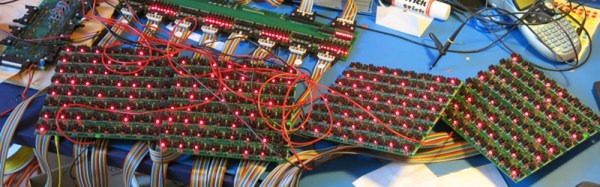
The switches are Cherry MX, the keys are from WASDkeyboards. [Vince] is actually getting a lot of interest in making modern ASCII keyboards to replace the old and busted boards that came in the home computers of the 70s and 80s. That might be a project [Vince] will release sometime in the future.

The Replica I, fully compatible Apple I replica

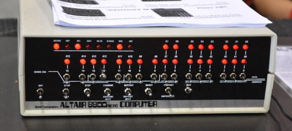
A much, much smaller version of the Altair

The Superboard III

MicroKIM
[Jef Raskin], the Swift Card, and the Canon Cat
[Steve Jobs] may have been the father of the Macintosh, but he was, by no means, solely responsible for the Mac. It was a team of people, and when you talk about the UI of the Mac, the first name that should come up is [Jef Raskin].
One of [Jef Raskin]’s finest works was the Swyft Card, an add-on to the Apple II that was basically just a ROM card that had an OS and Forth interpreter on it. The distinguishing feature of the Swyft card was the use of ‘leap’ keys, a simple way to change contexts when using the computer. We’ve seen replicas of the Swyft card before, courtesy of [Mike Willegal] at the Vintage Computing Festival East.
 [Dwight Elvey] of the vintage-computer.com forum brought a few extra special items related to [Raskin] and the Canon Cat. The first was a Swyft card installed in an Apple IIe. The second was a prototype Swyft computer, with SERIAL NUMBER 1 printed on a Dymo label and fixed to the case.
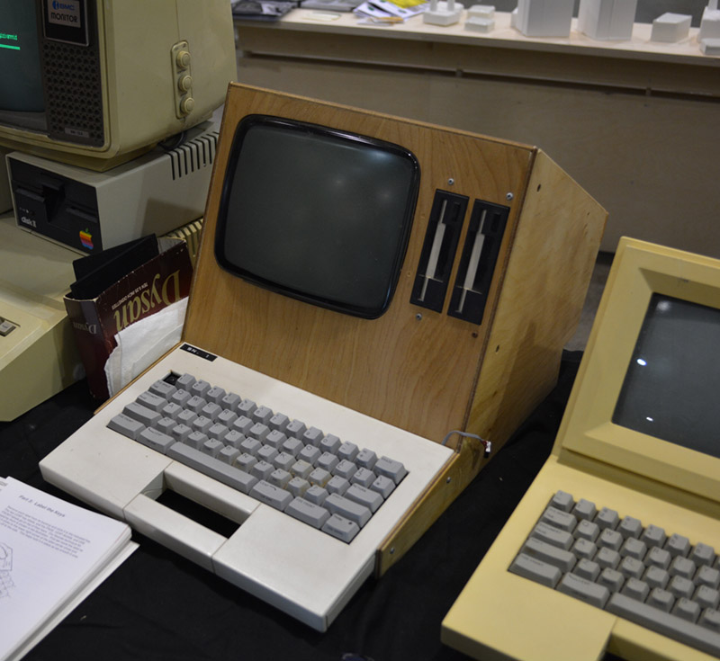
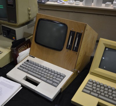
The ‘woodie’, as [Dwight] calls it, has two 1.44 MB disk drives, of which half of the disk is actually usable. [Dwight] didn’t take the machine apart, but I’m 99% sure the CRT in it is the exact same tube found in early 9″ Macs.
Also in [Dwight]’s display is a production Swyft computer and a Canon Cat, the final iteration of [Jef Raskin]’s idea of what a text-based computer should be.
The vintage-computer booth also had a few interesting retrocomputers including a Commodore 128D, the Apple made, Bell & Howell branded Apple II, and an Amiga 2000. Right next door was the Computer History Museum, who brought a very kid-friendly storage medium display. Showing a 10-year-old an 8″ disk is fun.

Bell & Howell branded Apple II

Leap keys for the Canon Cat

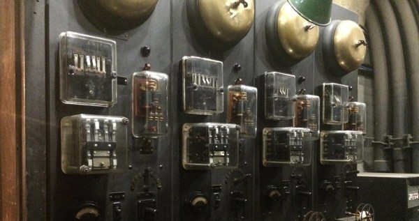
Analog computer from the Computer History Museum. It was display Chua’s Circuit.

Cat Keyboard
![A Collection of [Jef Raskin]'s work](https://i0.wp.com/hackaday.com/wp-content/uploads/2015/05/jef-raskin.jpg?w=477&h=212&ssl=1 "Jef Raskin")
A Collection of [Jef Raskin]’s work