Adding Crush Ribs To 3D Printed Parts For A Better Press Fit

[Dan Royer] shared a tip about how to get a reliably tight fit between 3D printed parts and other hardware (like bearings, for example.) He suggests using crush ribs, a tried-and-true solution borrowed from the world of injection molding and repurposed with 3D printing in mind. Before we explain the solution, let’s first look at the problem a little more closely.

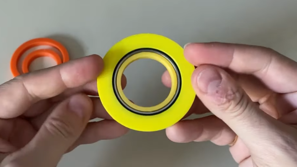
Imagine one wishes to press-fit a bearing into a hole. If that hole isn’t just the right size, the bearing won’t be held snugly. If the hole is a little too big, the bearing is loose. Too small, and the bearing won’t fit at all. Since a 0.1 mm difference can have a noticeable effect on how loose or snug a fit is, it’s important to get it right.

Crush rib locations highlighted with blue arrows.

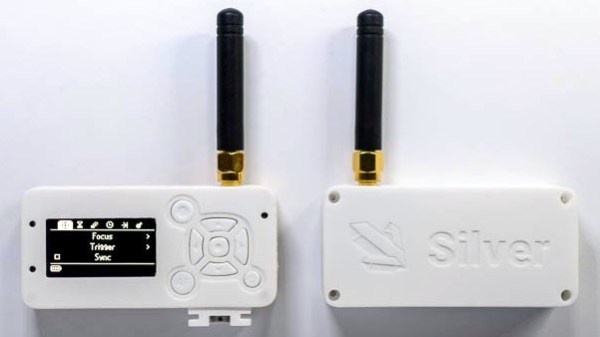
For a 3D printed object, a hole designed with a diameter of 20 mm (for example) will come out slightly different when printed. The usual way around this is to adjust printer settings or modify the object until the magic combination that yields exactly the right outcome is found, also known as the Goldilocks approach. However, this means the 3D model only comes out right on a specific printer, which is a problem for a design that is meant to be shared. Since [Dan] works on robots with 3D printed elements, finding a solution to this problem was particularly important.

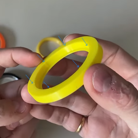
The solution he borrowed from the world of injection molding is to use crush ribs, which can be thought of as a set of very small standoffs that deform as a part is press-fit into them. Instead of a piece of hardware making contact with the entire inside surface of a hole, it makes contact only with the crush ribs. Press fitting a part into crush ribs is far easier (and more forgiving) than trying to get the entire mating surface exactly right.

Using crush ribs in this way is a bit of a hack since their original purpose in injection molding is somewhat different. Walls in injection-molded parts are rarely truly flat, because that makes them harder to eject from a mold. Surfaces therefore have a slight cant to them, which is called a draft. This slight angle means that press fitting parts becomes a problem, because any injection-molded hole will have slanted sides. The solution is crush ribs, which — unlike the walls — are modeled straight. The ribs are small enough that they don’t have an issue with sticking in the mold, and provide the mating surface that a press-fit piece of hardware requires. [Dan] has a short video about applying this technique to 3D printed objects, embedded below.

Continue reading “Adding Crush Ribs To 3D Printed Parts For A Better Press Fit”

Art of 3D printer in the middle of printing a Hackaday Jolly Wrencher logo

3D Printering: The World Of Non-Free 3D Models Is Buyer Beware

There are more free 3D models online than one can shake a stick at, but what about paid models? Hosting models somewhere and putting a buy button in front of the download is certainly a solved problem, but after spending some time buying and printing a variety of non-free 3D models online, it’s clear that there are shortcomings in the current system.

What the problems are and how to address them depends a little on the different ways models get sold, but one thing is clear: poorly-designed 3D models are bad for consumers, and bad for the future of pay-to-download in general. Continue reading “3D Printering: The World Of Non-Free 3D Models Is Buyer Beware”

Gain An Understanding Of Injection Molding’s Design Gotchas

When it comes to manufacturing, sheet metal and injection molding make the world go ’round. As a manufacturing method, injection molding has its own range of unique design issues and gotchas that are better to be aware of than not. To help with this awareness, [studiored] has a series of blog posts describing injection molding design issues, presented from the perspective of how to avoid and address them.

Design of screw bosses demonstrating conflict between molder’s guidelines and vendor’s recommendations. Compromising between both is a science and an art.

Because injection molding involves heat, warp is one issue to be aware of and its principles will probably be familiar to anyone with nitty-gritty experience in 3D printing. Sink marks are also an issue that comes down to differential cooling causing problems, and can ruin a smooth and glossy finish. Both of these play a role in how best to design bosses.

Minimizing and simplifying undercuts (similar to overhangs in 3D printer parlance) is a bit more in-depth, because even a single undercut means much more complex tooling for the mold. Finally, because injection molding depends on reliably molding, cooling, and ejecting parts, designing parts with draft (a slight angle to aid part removal) can be a fact of life.

[studiored] seems to have been working overtime on sharing tips for product design and manufacture on their blog, so it’s worth keeping an eye on it for more additions. We mentioned earlier that much of the manufacturing world revolves around injection molding and sheet metal, so to round out your knowledge we published a primer on everything you need to know about the art and science of bending sheet metal. With a working knowledge of the kinds of design issues that affect these two common manufacturing methods, you’ll have a solid foundation for any forays into either world.

How To Try Generative Optimization At Home

Chairs, spokes on a wheel, bridges, and all kinds of other load-bearing objects are designed such that material is only present where it is needed. There’s a process by which the decisions about how much material to put and where is determined by computer, and illustrating this is [Adam Bender]’s short primer on how to use generative optimization in Autodesk’s Fusion 360 (which offers a variety of free licenses) using a wheel as an example.

Things start with a solid object and a definition of the structural loads expected. The computer then simulates the force (or forces) involved, and that simulation can be used to define a part that only has material where it’s really needed. The results can be oddly organic looking, and this process has been used to optimize spacebound equipment where every gram counts.

It’s far from an automated process, but it doesn’t look too difficult to navigate the tools for straightforward designs. [Adam] cautions that one should always be mindful of the method of manufacturing when designing the part’s final form, which is always good advice but especially true when making oddball shapes and curves.  To see the short process in action, watch the video embedded below.

Continue reading “How To Try Generative Optimization At Home”

These Lessons Were Learned In Enclosure Design, But Go Far Beyond

[Foaly] has been hard at work making an open-source long range camera remote, and recently shared a deeply thoughtful post about how it is never too early to consider all aspects of design, lest it cost you in the end. It all started with designing an enclosure for a working prototype, and it led to redesigning the PCB from scratch. That took a lot of guts, and we recommend you make some time to click that link and read up on what he shared. You’ll either learn some valuable tips, or just enjoy nodding sagely as he confirms things you already know. It’s win-win.

Note the awkward buttons right next to the antenna connector, for example.

The project in question is Silver, and calling it a camera remote is selling it a bit short. In any case, [Foaly] had a perfectly serviceable set of prototypes and needed a small batch of enclosures. So far so normal, but in the process of designing possible solutions, [Foaly] ran into a sure-fire sign that a project is in trouble: problems cropping up everywhere, and in general everything just seeming harder than it should be. Holding the mounting-hole-free PCB securely never seemed quite right. Buttons were awkward to reach, ill-proportioned, and didn’t feel good to use. The OLED screen’s component was physically centered, but the display was off-center which looked wrong no matter how the lines of the bezel were sculpted. The PCB was a tidy rectangle, but the display ended up a bit small and enclosures always looked bulky by the time everything was accounted for. The best effort is shown here, and it just didn’t satisfy.

[Foaly] says the real problem was that he designed the electronics and did the layout while giving some thought (but not much thought) to their eventual integration into a case. This isn’t necessarily a problem for a one-off, but from a product design perspective it led to so many problems that it was better to start over, this time being mindful of how everything integrates right from the start: the layout, the components, the mechanical bits, the assembly, and the ultimate user experience. The end result is wonderful, and we’re delighted [Foaly] took the time to document his findings.

Enclosure design is a big deal and there are many different ways to go about it. For a more unique spin, be sure to check out our how-to make enclosures from the PCBs themselves. For a primer on more traditional enclosure manufacture and design, take a few minutes to familiarize yourself with injection molding.

Marketing And Selling Hardware Hack Chat

Join us Wednesday at noon Pacific time for the Marketing and Selling Hardware Hack Chat with Shawn Hymel!

It may not be every hardware hacker’s dream, but a fair number of us harbor fantasies of thinking up the Next Big Thing and kissing the day job goodbye forever. It’s an understandable dream and a laudable goal, but as they say, a goal is a dream with a plan and a deadline. What’s your plan for turning your project into a marketable product? Chances are good you don’t have one, and if you ever expect to get to your goal you’re going to need one.

Shawn Hymel is an engineer who led several marketing campaigns for Spark Fun and recently shared his thoughts on marketing with attendees of the first-ever KiCon conference in Chicago. He’ll be dropping by the Hack Chat to talk about everything you ever wanted to know about marketing your hardware projects but were afraid to ask.

join-hack-chat

Our Hack Chats are live community events in the Hackaday.io Hack Chat group messaging. This week we’ll be sitting down on Wednesday, May 8 at noon Pacific time. If time zones have got you down, we have a handy time zone converter.

Click that speech bubble to the right, and you’ll be taken directly to the Hack Chat group on Hackaday.io. You don’t have to wait until Wednesday; join whenever you want and you can see what the community is talking about.

Innovative Bird Feeder Design Recycles Recycling’s Garbage

Recycling beverage cartons isn’t 100% efficient. The process yields some unusable garbage as a byproduct. Why? Because containers like juice boxes are mostly paper, but also contain plastic and aluminum. The recycling process recovers the paper fibers for re-use, but what’s left after that is a mixture of plastic rejects and other bits that aren’t good for anything other than an incinerator or a landfill. Until now, anyway!

It turns out it is in fact possible to turn such reject material into a product that can be injection-molded, as shown here with [Stefan Lugtigheid]’s SAM bird feeder design. The feeder is not just made from 100% recycled materials, it’s made from the garbage of the recycling process — material that would otherwise be considered worthless. Even better, the feeder design has only the one piece. The two halves are identical, which reduces part count and simplifies assembly.

[Stefan] makes it clear that the process isn’t without its quirks. Just because it can be injection-molded doesn’t mean it works or acts the same as regular plastic. Nevertheless, the SAM birdfeeder demonstrates that it can definitely be put to practical use. We’ve seen creative reprocessing of PET bottles and sheet stock made from 3D printed trash, but recycling the garbage that comes from recycling drink cartons is some next-level stuff, for sure.