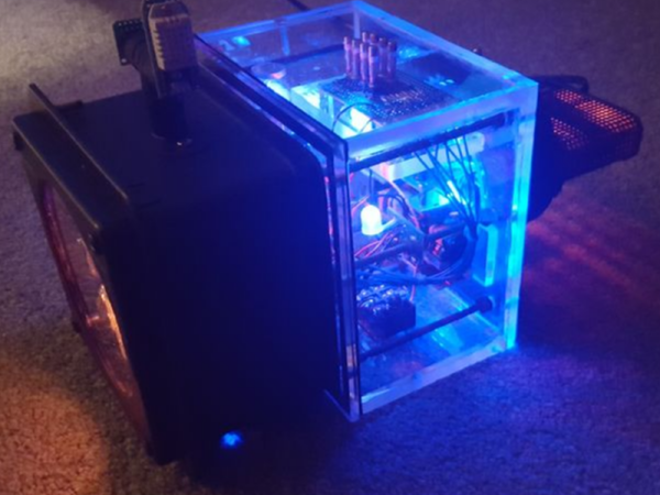
Ironically, with the wide availability of modular electronic components today, the hardest part of constructing your latest gadget might just end up being able to find a decent looking enclosure for it. Project boxes will only get you so far, and let’s be honest, they aren’t exactly the most attractive things in the world. But if you’re willing to think outside the box (get it?) there are some unconventional options out there that might fit the bill.
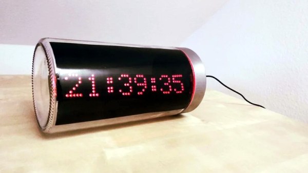
 Take for example this ESP8266 clock by [ZaNgAbY] that’s housed in a glass pasta jar. With the addition of some window tint film for the LED display to shine through, the final result could nearly pass as modern art. Even if you don’t need an extra clock around the house, this same general principle could be used to create a slick-looking ticker for all sorts of information, from the weather to server uptime with just some adjustments to the code.
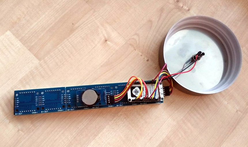
Inside the jar there’s six 8×8 MAX7219 LED matrix modules tacked together to create one long strip, with a NodeMCU board stuck to the back with double-sided tape. There’s also a DS3231 RTC module so the clock can keep halfway decent time, but depending on how aggressively you are willing to pull down the current time from NTP, that may or may not be required. A simple barrel jack is popped through the metal lid of the jar for power, and represents the only physical connection the internals have to the outside world.
For the next iteration [ZaNgAbY] is thinking of adding a temperature and humidity sensor, and a light sensor that can dim the LED display depending on the ambient light. While the environmental sensors will have to go on the outside of the lid if there’s any hope of pulling useful readings from them, the clear glass will allow him to keep the light sensor internal to the clock.
Believe it or not, this isn’t the first time we’ve seen somebody give their electronics the pickle treatment. We’ve previously played host to a server that “preserves” files in a Mason jar, as well as a gorgeous display of an iPod under glass.
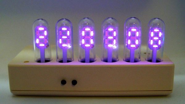


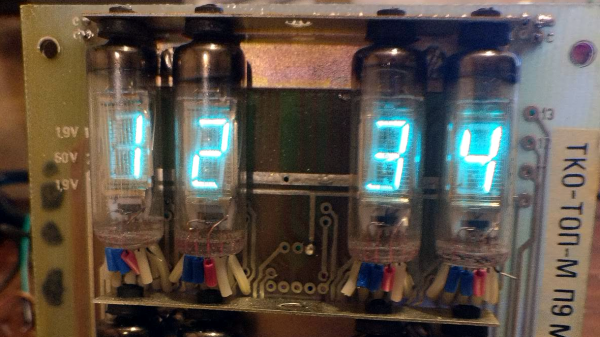
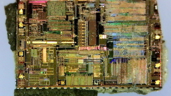
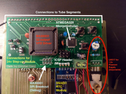 After getting the VFDs lighting up and figuring out the circuitry on the back, [InThePartsBin] decided that a clock was the best thing to build out of it. It was decided that a specialized VFD driver chip was the easiest way to make the thing work, so a MAX6934 was ordered. To give the clock some brains, an ATmega328 was recruited and to keep time, [InThePartsBin] had some DS3231 real-time clock modules left over from a previous project, so they were recruited as well. A daughterboard was designed to sit on the back of the vintage board and hold the ‘328 and the VFD driver chip.
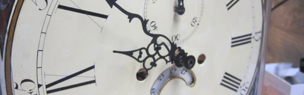
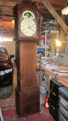 He starts off by building a custom electro-mechanical clock movement, and since he’s planning as he progresses, meccano, breadboard and jumper wires were the way to go. Hot glue helps preserve sanity by keeping all the jumper wires in place. To interface with all of the peripherals in the clock, he decided to use a bank of shift registers driven from a regular Arduino Uno. The more expensive DS3231 RTC module ensures better accuracy compared to the cheaper DS1307 or similar clones. A bank of RGB LEDs acts as an annunciator panel inside the clock to help provide various status indications. The mechanical movement itself went through several iterations to get the time display working with a smooth movement of the hands. Besides displaying time, [David] also added a moon phase indicator dial. A five-rod chime is struck using a stepper motor driven cam and a separate solenoid is used to pull and release three chime hammers simultaneously to generate the loud gong sounds.