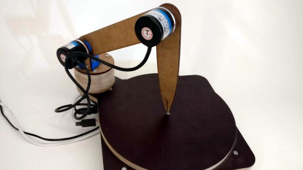
Roll Your Own Rotary Encoders

[miroslavus] hasn’t had much luck with rotary encoders. The parts he has tested from the usual sources have all been problematic either mechanically or electrically, resulting in poor performance in his projects. Even attempts to deal with the deficiencies in software didn’t help, so he did what any red-blooded hacker would do — he built his own rotary encoder from microswitches and 3D-printed parts.

[miroslavus]’s “encoder” isn’t a quadrature encoder in the classic sense. It has two switches and only one of them fires when it turns a given direction, one for clockwise and one for counterclockwise. The knob has a ratchet wheel on the underside that engages with a small trip lever, and carefully located microswitches are actuated repeatedly as the ratchet wheel moves the trip lever. The action is smooth but satisfyingly clicky. Personally, we’d forsake the 3D-printed baseplate in favor of a custom PCB with debouncing circuitry, and perhaps relocate the switches so they’re under the knob for a more compact form factor. That and the addition of another switch on the shaft’s axis to register knob pushes, and you’ve got a perfectly respectable input device for navigating menus.

We think this is great, but perhaps your project really needs a legitimate rotary encoder. In that case, you’ll want to catch up on basics like Gray codes.

Continue reading “Roll Your Own Rotary Encoders”

Scrap A Hard Drive, Build A Rotary Encoder

There’s something to be said for the feel of controls. Whether it’s the satisfying snap of a high-quality switch or the buttery touch of the pots on an expensive amplifier, the tactile experience of the controls you interact with says a lot about a device.

[GreatScott!] knows this, and rather than put up with the bump and grind of a cheap rotary encoder, he decided to find an alternative. He ended up exploring hard drive motors as encoders, and while the results aren’t exactly high resolution, he may be onto something. Starting with a teardown of some old HDDs — save those magnets! — [Scott!] found that the motors fell into either the four-lead or three-lead categories. Knowing that HDD motors are brushless DC motors, he reasoned that the four-lead motors had their three windings in Wye configuration with the neutral point brought out to an external connection. A little oscilloscope work showed the expected three-phase output when the motor hub was turned, with the leading and lagging phases changing as the direction of rotation was switched. Hooked to an Arduino, the motor made a workable encoder, later improved by sending each phase through a comparator and using digital inputs rather than using the Nano’s ADCs.

It looks like [GreatScott!]’s current setup only responds to a full rotation of the makeshift encoder, but we’d bet resolution could be improved. Perhaps this previous post on turning BLDC motors into encoders will help.

Continue reading “Scrap A Hard Drive, Build A Rotary Encoder”

Add Intuitiveness To OpenSCAD With Encoders

The first time I saw 3D modeling and 3D printing used practically was at a hack day event. We printed simple plastic struts to hold a couple of spring-loaded wires apart. Nothing revolutionary as far as parts go but it was the moment I realized the value of a printer.

Since then, I have used OpenSCAD because that is what I saw the first time but the intuitiveness of other programs led me to develop the OpenVectorKB which allowed the ubiquitous vectors in OpenSCAD to be changed at will while keeping the parametric qualities of the program, and even leveraging them.

All three values in a vector, X, Y, and Z, are modified by twisting encoder knobs. The device acts as a keyboard to

  1. select the relevant value
  2. replace it with an updated value
  3. refresh the display
  4. move the cursor back to the starting point

There is no software to install and it runs off a Teensy-LC so reprogramming it for other programs is possible in any program where rotary encoders may be useful. Additional modes include a mouse, arrow keys, Audacity editing controls, and VLC time searching.

Here’s an article in favor of OpenSCAD and here’s one against it. This article does a good job of explaining OpenSCAD.

Continue reading “Add Intuitiveness To OpenSCAD With Encoders”

Reading 16 Rotary Encoders At The Same Time

We’re digging these daisy-chainable encoders built by [fattore.saimon]. Each module consists of a rotary encoder attached to a PCB with a PIC16F15386 on the back. As we’ve covered in the past, the Microchip released their feature-rich PIC16 microprocessor just this year, and it’s great to see them start to crop up in projects. With 4 address jumpers on the back of each PCB, [fattore.saimon] is able to connect up to 16 of the encoders on the bus. The modules also have male and female plugs so he can connect them physically as well, to simplify wiring. Each module also has a PWMable bicolor LED for keeping track of each encoder’s setting.

If you’re interested in making your own you can buy the PCBs from Tindie or download the project files from the creator’s GitHub, including an Arduino library.

We love encoders here on Hackaday — building DIY encoders, as well as using them in projects like this precision cutting jig. And definitely read our colleague [Al]’s great piece on encoders.

In-Band Signaling: Coded Squelch Systems

In the first part of our series on in-band signaling, we discussed one of the most common and easily recognizable forms of audio control, familiar to anyone who has dialed a phone in the last fifty years – dual-tone multifrequency (DTMF) dialing. Our second installment will look at an in-band signaling method that far fewer people have heard, precisely because it was designed to be sub-audible — coded squelch systems for public service and other radio services. Continue reading “In-Band Signaling: Coded Squelch Systems”

In-Band Signaling: Dual-Tone Multifrequency Dialing

One late night many decades ago, I chanced upon a technical description of the Touch-Tone system. The book I was reading had an explanation of how each key on a telephone sends a combination of two tones down the wire, and what’s more, it listed the seven audio frequencies needed for the standard 12-key dial pad. I gazed over at my Commodore 64, and inspiration hit — if I can use two of the C64’s three audio channels to generate the dual tones, I bet I can dial the phone! I sprang out of bed and started pecking out a Basic program, and in the wee hours I finally had it generating the recognizable Touch-Tones of my girlfriend’s phone number. I held the mouthpiece of my phone handset up to the speaker of my monitor, started the program, and put the receiver to my ear to hear her phone ringing! Her parents were none too impressed with my accomplishment since it came at 4:00 AM, but I was pretty jazzed about it.

Since that fateful night I’ve always wondered about how the Touch-Tone system worked, and in delving into the topic I discovered that it’s part of a much broader field of control technology called in-band signaling, or the use of audible or sub-audible signals to control an audio or video transmission. It’s pretty interesting stuff, even when it’s not used to inadvertently prank call someone in the middle of the night. Continue reading “In-Band Signaling: Dual-Tone Multifrequency Dialing”

3DP Enigma Keyboard Improves On The Original

[Asciimation], who previously created an Enigma Machine wristwatch, decided to go all-in and make a 3D-printed Enigma machine. Not a perfect replica, but rather an improved version that works the same but doesn’t concern itself with historical accuracy. For instance, the current step involves building the keyboard. Rather than trying to re-create the spring-and-pin method of the original, he simply swapped in readily available, double-throw micro switches.

This project has a tremendous amount of fascinating detail. [Asciimation] did his research and it shows; he downloaded blueprints of the original and used hacked digital calipers to precisely measure each rotor’s teeth, so that it could be re-created for printing. He even re-created the Enigma font to ensure that his printed rotor wheels would look right–though in doing so he discovered that the original machine used one typeface for the keyboard, one for the wheels, and one for the indicator lamps.

We previously published [Asciimation]’s Enigma machine wristwatch project, where he simulated the functionality of an Enigma with an Arduino.

Continue reading “3DP Enigma Keyboard Improves On The Original”