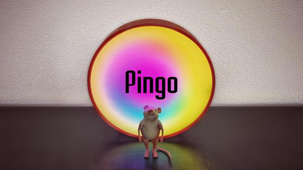
The purpose of a clock is to show the time, obviously. But if you’ve followed Hackaday for some time, you’ll know there are about a million different ways of achieving this. [illusionmanager] added yet another method in his Pingo Color Clock, which, as the name suggests, uses color as the main indicator.
The clock’s face is divided into three concentric circular zones. The zone at the center shows the hours, while the outer ring indicates the minutes. Both change their color such that they match the zone in between, which always shows a complete rainbow, at the desired location. In the picture above for example, the magenta inner circle matches the rainbow at the 10 o’clock position, while the yellow outer circle matches it at 10 minutes past the hour, meaning it’s currently 10:10.
 The rainbow ring is also moving however, and by adjusting its rotation through time you can get some interesting effects. [illusionmanager] programmed it in such a way that the outer ring is always yellow during the day, purple at night, and red at sunrise and sunset. The overall brightness is also adjusted to a day/night schedule.
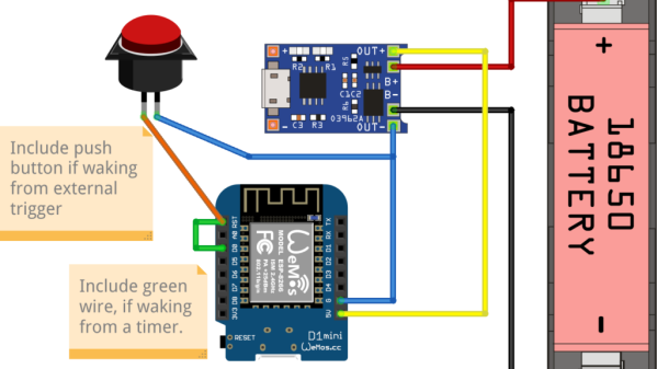
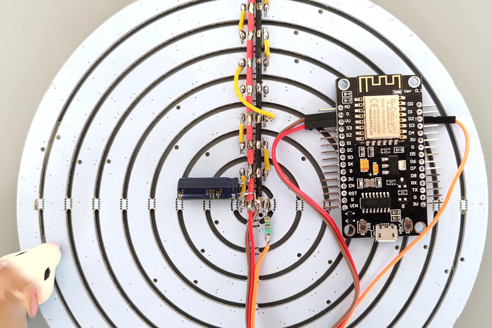
As complex as the clock’s appearance may be, inside it’s quite a simple design. Nine concentric circular LED strips are driven by an ESP8266, which retrieves the time and sunrise information through its WiFi connection. A piece of translucent white acrylic acts as a diffuser, while a 3D-printed enclosure holds everything together.
Encoding the time using different colors of light has been done before in various different ways, and while we haven’t seen Pingo in real life, we believe it should be somewhat easier to read than most of those examples. It might actually form a nice complement to a recent analog LED ring clock.
Continue reading “Pingo Is An Analog Clock That Uses Colors Instead Of Hands”