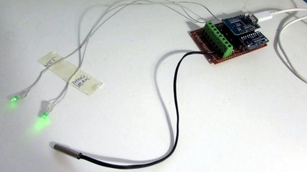
Section from the ESP8266 datasheet, showing maximum input voltage as 3.6V, but not mentioning ESD diodes to VCC and only talking about a snap-back circuit set to 6V.

Is ESP8266 5 V Tolerant? This Curve Tracer Says Yes!

Some people state that ESP8266 is tolerant of 5 V logic levels on its GPIOs, while others vehemently disagree, pointing at the datasheet-stated 3.6 V maximum. Datasheets aren’t source code for compiling the chip, however, and aren’t universally correct and complete either. [Avian] decided to dig deeper into the claims, conduct an experiment with an actual ESP8266 chip, then share the results for all of us.

For the experiment, he used a curve tracer – a device capable of producing a wide range of voltages and measuring the current being consumed, then plotting the voltage-to-current relationship. This helps characterize all sorts of variables, from diode breakdown voltages to transistor characteristics. The curve tracer he uses is a capable and professional-looking DIY build of his, and arguably, deserves a separate write-up!

The reasoning behind [Avian]’s experiment is simple – if the pin, set to an input, starts consuming a higher amount of current at a certain voltage threshold, then there’s gotta be some chip-internal structure, intended or unintended, that would be damaged at this voltage. Curve tracer in hand, he set up an ESP-01 module to set a GPIO to input, and started increasing the voltage.

A curve tracer output graph, showing that there's no noticeable increase of current consumed across the range of 0V to 6.6V - current increasing from 0.2mA to 0.4mA in that range

The tests have shown that, while there’s a reverse biased ESD diode from GPIO pins to ground, there don’t seem to be diodes from the GPIO pin to the VCC rail – and those are the primary concern for 5 V tolerance. There does seem to be something functionally akin to a 6 V Zener diode internally, which should clamp the voltage before it gets too way high for the chip to handle. None of that should be a problem for 5 V compatibility, and it seems fair to interpret this as a confirmation of 5 V tolerance until someone shows otherwise.

[Avian] didn’t want to destroy an ESP8266, so the experiment was conducted with a 1 K series resistor between the curve tracer and the input – which might have biased the results a bit. On the other hand, adding series resistors in front of your inputs is an overall underappreciated practice, 5 V or otherwise. He also points out that, while the pins don’t seem to be adversely impacted by the higher input voltage, the bootloader might set some of them to 3.3 V outputs on boot-up, shorting your 5 V source to your 3.3 V rail — worth keeping in mind!

[Avian]’s research journeys are fun to follow, and we recommend you check his blog out; last time, we covered his research of an innocent-looking 3.5 mm jack hiding a devious audio compensation circuit. Since we first covered the ESP8266 in 2014, we’ve been researching all the things it’s really capable of, and we brought up the topic of GPIO 5 V compatibility way back in 2016 – it’s reassuring to finally put this question to rest!

We thank [Adrian] for sharing this with us!

Engineering On A Deadline For Squid Game

If you asked us for an epic tale of designing and building under a deadline, one of the last places we would think to look is a MrBeast video.  Yet here we are, thanks in no small part to the epic skills of one [William Osman].

What do you do when a major YouTube celebrity asks you to handle a project with an impossible deadline?  If you’re [William], you say “heck yeah” and figure out the details later. In this case, it was famed YouTuber [Jimmy Donaldson], aka MrBeast, who was planning his own version of Squid Game. In this version, no one dies, but a few players do walk away with a lot of cash.

The premise is simple — “kill” people with a motion-sensing gun turret, just like the one in the show. The problem is that the show had all the tools of movie magic – multiple takes, video editing, you name it. [William] was tasked with handling a live event, with 456 real people, and no do-overs. Oh, and the whole thing had to be ready in 3 weeks.

The kills had to be pretty obvious too – we’re talking simulated blood squirting everywhere. So [William] decided to build his own version of a blood squib – the device Hollywood has used for decades to simulate bullet wounds. Initial work with pneumatic systems proved to be impractical. That’s when he put on his manager hat — and hired people to solve the problem for him. You might recognize a few of them — [Allen Pan] makes an appearance, as well as chemical genius [NileRed]. Even [TheBackYardScientist] shows up.

The video documents [William]’s journey, getting 500 copies of a board built and delivered on deadline. As such, there isn’t a ton of detail about the internal workings of the system. A pair of AA batteries feed into a boost converter, which powers an ESP8266 inside an ESP-WROOM-02 module. The ESP drives a few LEDs and a MOSFET. The MOSFET is connected to the star of the show – an MGJ firewire initiator – think of it as a model rocket igniter on steroids.  The initiator hides behind a bag of YouTube-friendly yellow “blood”. When the system is commanded to kill, the initiator pops the bag, spraying blood everywhere.

Doing this for one device isn’t so bad, but we’re following Squid Game rules – which means 456 competitors. Further, there were 100 iPhones loaded with a custom kill app for the workers. Add a central server into the mix, and you’ve got 557 devices in close quarters basting on 2.4 GHz and 5.8 GHz. Did we mention that [William] had never done a test with more than a handful of devices?

Want to find out what happens? Check out the video below!

Continue reading “Engineering On A Deadline For Squid Game

Reversible Ventilation Hack Keeps The Landlord Happy

When a person owns the home they live in, often the only approval they need for modifications is from their significant other or roommate. In the worst case, maybe a permit is required. But those who rent their dwellings are far more constrained in almost every case, and when it comes to environmental controls, they are most decidedly off limits. Unless you’re a resourceful hacker like [Nik], that is, who has seamlessly integrated his apartment’s ventilation system into his smart home controller — all without any permanent modifications!

The controller itself only gives three settings to vent the apartment: Low, Medium, High, and then High for 30 minutes, with all modes having to be actuated with a manual button press. [Nik] wanted automation and integration with his smart home.

A clean 3D printed enclosure wraps things nicely

Thankfully, the engineers who designed the controller used in [Nik]’s apartment made it very convenient to reverse engineer it. A flat ribbon cable conveniently breaks out all of the buttons and 12 VDC, and he can interface directly using its connector. First hack: done.

Next, [Nik] needed a longer cable to run between the controller and his ESP8266 based control module. Finding the connector on AliExpress was easy, but finding a compatible cable of length required some more resourcefulness. The cable was eventually sourced from the airbag controller of a Renault Megane! Second hack, using a car part in a controller: well done!

Integration into his smart home wasn’t just electronic. The module looks right at home above the original controller, and if you didn’t know better you’d never think it wasn’t original equipment. Final hack: Done!

Be sure to check out his build log over at Hackaday.io, and if home automation hacks are your cup of tea, check out this automatic tea maker.

RFM9x module held in an adapter board with flexipins

FlexyPins Might Help With Those Pesky Castellated Modules

[SolderParty] just announced FlexyPins (Twitter, alternative view) – bent springy clips that let you connect modules with castellated pins. With such clips, you can quickly connect and disconnect any castellated module, swapping them without soldering as you’re prototyping, testing things out, or pre-flashing modules before assembly. They’re reportedly gold-plated, and a pack of ~100 will set you back 6EUR, shipping not included.

Of course, this is basically “fancy pieces of wire”, purpose-shaped, gold-plated and, hopefully, made out of material that is springy enough and doesn’t snap easily after bending a few times. We’ve seen this concept used for prototyping before, with random pieces of wire doing a pretty good job of maintaining connectivity, but these clips bring it that much closer to production-grade. It also makes us wonder – just how hard it is to solder 30-40 of them into a circuit? Do they self-align enough with the footprints given, or do you have to hold them with tweezers at a peculiar angle as you solder them? Time will tell, of course.

Continue reading “FlexyPins Might Help With Those Pesky Castellated Modules”

An Off-Grid Makeshift Cell Network

When traveling into the wilderness with a group of people, it’s good to have a method of communications set up both for safety and practicality. In the past people often relied on radios like FRS, CB, or ham bands if they had licenses, but nowadays almost everyone has a built-in communications device in their pocket that’s ready to use. Rather than have all of his friends grab a CB to put in their vehicle for their adventures together, [Keegan] built an off-grid network which allows any Android phone to communicate with text even if a cell network isn’t available.

The communications system is built on the LoRa communications standard for increased range over other methods like WiFi using a SX1278 chip and an ESP8266. The hardware claims a 10 km radius using this method which is more than enough for [Keegan]’s needs. Actually connecting to the network is only half of the solution though; the devices will still need a method of communication. For that, a custom Android app was created which allows up to 8 devices to connect to the network and exchange text messages with each other similar to a group text message.

For off-grid adventures a solution like this is an elegant solution to a communications problem. It uses mostly existing hardware since everyone carries their own phones already, plus the LoRa standard means that even the ESP8266 base station and transmitter are using only a tiny bit of what is likely battery power. If you’re new to this wireless communications method, we recently featured a LoRa tutorial as well.

Belgian Railway Time For Your Home

Some of the 20th century’s most iconic design and typography came to us through public signage in the various national railways of Europe. Were you to think of a Modernist clock face for example, the chances are that the prototype for your image hangs somewhere in one of the continent’s great railway terminals. If you don’t fancy getting on a train to see your favourite public timepiece, then maybe [EBP Controller] has a treat for you, with a 3D-printed double-faced Belgian railway station clock.

Behind the scenes the mechanism is simpler than appearances might lead the observer to believe, with each set of hands driven through a single gear to a motor. Controlling it all is an ESP8266, which is able to synchronise the clock exactly to an NTP server. It appears at first sight to have an unnecessarily large quantity of motors, but considering that there are two faces each with three hands the six motors each have a use. So while the real thing might require a heist from the SNCB, at least modernist clock fans can now have their own.

ESP8266 Based WiFi Game Boy Cartridge Browses WikiPedia

[Sebastian Staacks] came across his old Game Boy and was wondering (as you do) what happened to recent attempts at getting a WiFi interface wedged into a standard cartridge. After a while the conclusion was that people had been scuppered by approaching the problem in a way that made it too hard. Obviously that meant it was necessary to follow through and build something, which is precisely what he did with his WiFi Game Boy Cartridge.

A trend lately has been to hook up a fast microcontroller to a bus, then move the whole interfacing shenanigans into software. This works fine in some circumstances, but for the GB interface, it’s not so easy. The GB is powered by the Sharp LR35902, running at a smidge over 4 MHz, but its machine cycle takes four clocks giving an instruction rate of only 1 MHz. The cartridge interface presents the raw CPU bus directly. This is both good and bad. It’s good, because it enables all kinds of expansion modules, like cameras, printers, and other custom peripherals, but it’s bad because the burden of interfacing with the CPU, at its full speed, lies squarely in the cartridge’s remit.

Rather than trying to hook this bus directly to a fast microcontroller, [Staacks] has taken a different approach; by decoding the address bus with discrete logic, it was easy to derive chip selects for an embedded ESP8266 as well as a socketed EEPROM. The clock for the former was also gated and sent into the ESP8266, generating an interrupt to wake it up. The EEPROM stores a simple application whose job is to present an OSD keyboard and send requests to Wikipedia, via the ESP8266 WiFi stack. The resulting text is then displayed on the 160×144 dot matrix display. The interrupt latency of the ESP8266 was mitigated by the application simply discarding the first data byte sent to it, and retrying the access. This way the ESP8266 could spend the majority of its time dealing with wireless duties, only pausing to swap a byte now-and-then with the application. A simple solution which appears to actually work! If you’re up for building one of these and writing your own applications, you can wander over to GitHub, clone yourself a copy and crack on!

We’ve seen a few attempts at doing this before, [davedarko] tried with this project, and if you search hackaday.io you’ll get loads of GB hacks to browse. Finally a recent twitter thread also points to another effort to do something similar with Wi-Fi, but development is still ongoing. We’ll check back later!

Continue reading “ESP8266 Based WiFi Game Boy Cartridge Browses WikiPedia”