3D-printed wall builder, circa 1930s

Retrotechtacular: 3D-Printed Buildings, 1930s Style

Here we are in the future, thinking we’re so fancy and cutting edge with mega-scale 3D printers that can extrude complete, ready-to-occupy buildings, only to find out that some clever inventor came up with essentially the same idea back in the 1930s.

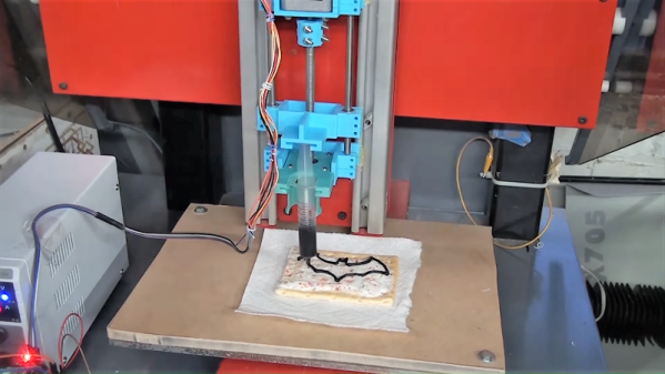
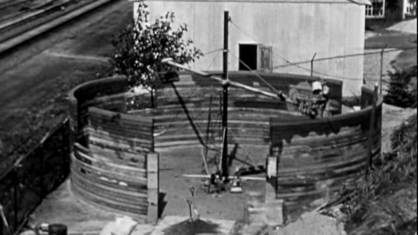
The inventor in question, one [William E. Urschel] of Valparaiso, Indiana, really seemed to be onto something with his “Machine for Building Walls,” as his 1941 patent describes the idea. The first video below gives a good overview of the contraption, which consists of an “extruder” mounted on the end of a counterweighted boom, the length of which determines the radius of the circular structure produced. The boom swivels on a central mast, and is cranked up manually for each course extruded. The business end has a small hopper for what appears to be an exceptionally dry concrete or mortar mix. The hopper has a bunch of cam-driven spades that drive down into the material to push it out of the hopper; the mix is constrained between two rotating disks that trowel the sides smooth and drive the extruder forward.

The device has a ravenous appetite for material, as witnessed by the hustle the workers show keeping the machine fed. Window and door openings are handled with a little manual work, and the openings are topped with lintels to support the concrete. Clever tools are used to cut pockets for roof rafters, and the finished structure, complete with faux crenellations and a coat of stucco, looks pretty decent.

Continue reading “Retrotechtacular: 3D-Printed Buildings, 1930s Style”

Modified 3D-Printer Solders Through-Hole Components

Surface-mount technology has been a fantastic force multiplier for electronics in general and for hobbyists in particular. But sometimes you’ve got no choice but to use through-hole components, meaning that even if you can take advantage of SMDs for most of the design, you still might need to spend a little time with soldering iron in hand. Or not, if you’ve got a spare 3D printer lying around.

All we’ve got here is a fairly brief video from [hydrosys4], so there aren’t a lot of build details. But it’s pretty clear what’s going on here. Starting with what looks like a Longer LK4 printer, [hydrosys4] added a bracket to hold a soldering iron, and a guide for solder wire. The solder is handled by a more-or-less standard extruder, which feeds it into the joint once it’s heated by the iron. The secret sauce here is probably the fixturing, with 3D-printed jigs that hold the through-hole connectors in a pins-up orientation on the bed of the printer. With the PCB sitting on top of the connectors, it’s just a matter of teaching the X-Y-Z position of each joint, applying heat, and advancing the solder with the extruder.

The video below shows it in action at high speed; we slowed it down to 25% to get an idea of how it is in reality, and while it might not be fast, it’s precise and it doesn’t get tired. It may not have much application for one-off boards, but if you’re manufacturing small PCB runs, it’s a genius solution. We’ve seen similar solder bots before, but hats off to [hydrosys4] for keeping this one simple.

Continue reading “Modified 3D-Printer Solders Through-Hole Components”

Hackaday Podcast 076: Grinding Compression Screws, Scratching PCBs, And Melting Foam

Hackaday editors Elliot Williams and Mike Szczys are enamored by this week’s fabrication hacks. There’s a PCB mill that isolates traces by scratching rather than cutting. You won’t believe how awesome this angle-cutter jig is at creating tapered augers for injection molding/extruding plastic. And you may not need an interactive way to cut foam, but the art from the cut pieces is more than a mere shadow of excellence. Plus we gab about a clever rotary encoder circuit, which IDE is the least frustrating, and the go-to tools for hard drive recovery.

Take a look at the links below if you want to follow along, and as always, tell us what you think about this episode in the comments!

Take a look at the links below if you want to follow along, and as always, tell us what you think about this episode in the comments!

Direct download (60 MB or so.)

Continue reading “Hackaday Podcast 076: Grinding Compression Screws, Scratching PCBs, And Melting Foam”

Make Your Own Filament

According to [Alex] it is easy to make your own rolls of 3D printing filament, even though existing off-the-shelf solutions don’t work very well. His explanation for this is economics. He built a filament extruder using a high torque induction motor and gearbox that was locally sourced. He argues that shipping heavy gear around would make a similar extruder commercially unattractive. He sunk about $600 into the device but estimates that a company would need to charge at least $1,500 or more for the same thing. That may seem steep but as [Alex] points out, a 1 kg roll of filament really only has about 750 grams for filament and plastic pellets cost $2 to $3 per kilogram.

There are other costs, of course, like the electricity required to heat and move the plastic. Still, the system appears to use about $1 of electricity for every 10 kg of filament. You can see the process in the video below.

Continue reading “Make Your Own Filament”

External Buffer Boosts 3D Printer Filament Splicing On The Palette 2

There was a time when most of us thought the next logical step for desktop 3D printing was to add additional extruders and hotends, allowing the machine to print in multiple colors or materials. Unfortunately such arrangements quickly become ungainly, and even with just two extruders, calibration can be a nightmare. Because of this, development has been trending towards systems that use just one hotend and simply alternate the filament being fed into it. But such systems have their own problems.

Arguably the biggest issue is how long it takes to switch filaments. The Palette 2 uses a physical buffer of spliced filament to try and keep ahead of the printer, but as [Kurt Skauen] demonstrates, there are considerable performance gains to be had by building a bigger buffer. He says there’s still some calibration issues to contend with, but judging by the video after the break, we’d say he is certainly on the right track.

The buffer is necessary to give the spliced filament time to cool and bond before being fed into the printer, but as currently designed, the machine simply can’t store enough of it to keep up with high print speeds. The stock buffer area holds 125mm worth of spliced filament, but the modification [Kurt] has designed adds a whopping 280mm on top of that to reach more than three times the stock capacity.

He’s successfully tested printing at speeds as high as 200mm/s with his upgraded buffer, a big improvement over what he was seeing with the original buffer area. This despite the fact that Mosaic (the company that produces the Palette) claim the original buffer size was already more than sufficient. It seems we’ve found ourselves in the middle of a debate between Mosaic and some very vocal members of the community, and while we don’t want to take sides, it’s hard to ignore [Kurt]’s findings.

Want to make your own? [Kurt] has released all the information necessary for others to duplicate his work, including the STLs for all printed parts and a list of the bearings, springs, and fasteners you’ll need to put it together. It looks like a fairly large undertaking, but with the potential for such a considerable speed boost, we don’t doubt others will be willing to take the plunge. One person who printed and assembled an earlier version of the buffer upgrade reports their print speeds with a 0.8 mm nozzle have more than doubled.

The Palette has come a long way from we first saw it in 2016, and since then, Prusa has thrown their orange hat into the ring with their own filament-switching upgrade. Neither machine is without its niggling issues, but they’re still probably our best shot at taking desktop 3D printing to the next level.

Continue reading “External Buffer Boosts 3D Printer Filament Splicing On The Palette 2”

Syringe Pump Turns CNC Machine Into A Frosting Bot

“Amazing how with only the power of 3D-printing, two different computers, hundreds of dollars in CNC machinery, a lathe, and modern microcontroller magic, I can almost decorate a cupcake as well as a hyperactive ten-year-old.”  We can think of no better way to sum up [Justin]’s experiment in CNC frosting application, which turns out to only be a gateway to more interesting use cases down the road.

Granted, it didn’t have to be this hard. [Justin] freely admits that he took the hard road and made parts where off-the-shelf components would have been fine. The design for the syringe pump was downloaded from Thingiverse and does just about what you’d expect – it uses a stepper motor to press down on the plunger of a 20-ml syringe full of frosting. Temporarily attached in place of the spindle on a CNC router, the pump dispenses onto the baked goods of your choice, although with an irregular surface like a muffin top the results are a bit rough. The extruded frosting tends to tear off and drop to the surface of the cake, distorting the design. We’d suggest mapping the Z-height of the cupcake first so the frosting can dispense from a consistent height.

Quality of the results is not really the point, though. As [Justin] teases, this hardware is in support of bioprinting of hydrogels, along with making synthetic opals. We’re looking forward to those projects, but in the meantime, maybe we can all just enjoy a spider silk beer with [Justin].

Continue reading “Syringe Pump Turns CNC Machine Into A Frosting Bot”

Assessing Nozzle Wear In 3D-Printers

How worn are your nozzles? It’s a legitimate question, so [Stefan] set out to find out just how bad 3D-printer nozzle wear can get. The answer, as always, is “It depends,” but exploring the issue turns out to be an interesting trip.

Reasoning that the best place to start is knowing what nozzle wear looks like, [Stefan] began by printing a series of Benchies with brand-new brass nozzles of increasing diameter, to simulate wear. He found that stringing artifacts, interlayer holes, and softening of overhanging edges and details all worsened with increasing nozzle size. Armed with this information, [Stefan] began a torture test of some cheap nozzles with both carbon-fiber filament and a glow-in-the-dark filament, both of which have been reported as nozzle eaters. [Stefan] found that to be the case for at least the carbon-fiber filament, which wore the nozzle to a nub after extruding only 360 grams of material.

Finally, [Stefan] did some destructive testing by cutting used nozzles in half on the mill and looking at them in cross-section. The wear on the nozzle used for carbon-fiber is dramatic, as is the difference between brand-new cheap nozzles and the high-quality parts. Check out the video below and please sound off in the comments if you know how that peculiar spiral profile was machined into the cheap nozzles.

Hats off to [Stefan] for taking the time to explore nozzle wear and sharing his results. He certainly has an eye for analysis; we’ve covered his technique for breaking down 3D-printing costs in [Donald Papp]’s  “Life on Contract” series.

Continue reading “Assessing Nozzle Wear In 3D-Printers”