Cheap And Easy Magnetic DNA Separation Method Needs Your Help

When you consider that almost every single cell in your body has more than a meter of DNA coiled up inside its nucleus, it seems like it should be pretty easy to get some to study. But with all the other cellular gunk in a crude preparation, DNA can be quite hard to isolate. That’s where this cheap and easy magnetic DNA separation method comes in. If it can be optimized and tested with some help from the citizen science community.

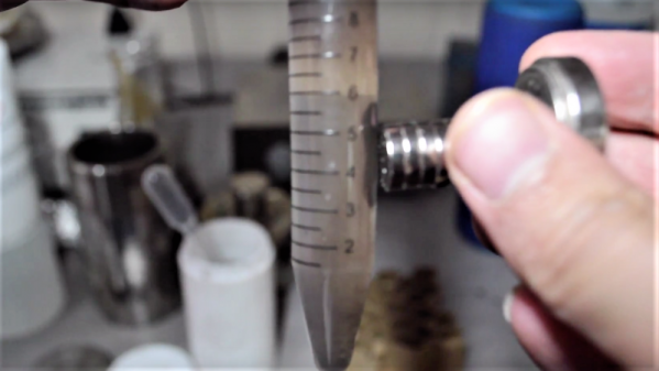
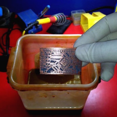
Commercial DNA separation methods generally involve mixing silica beads into crude cell fractions; the DNA preferentially binds to the silica, making it possible to mechanically separate it from the rest of the cellular junk. But rather than using a centrifuge to isolate the DNA, [Justin] from The Thought Emporium figured that magnets might do a better job. It’s not a new idea — biotech companies offer magnetic separation beads commercially, but at too steep a price for [Justin]’s budget. His hack comes from making magnetite particles from common iron compounds like PCB etchant and moss killer, and household ammonia cleaner. The magnetite particles are then coated with sodium silicate solution, also known as waterglass. The silica coating should allow the beads to bind to DNA, with the magnetic core taking care of separation.

[Justin] was in the process of testing his method when he lost access to the needed instruments, so he’s appealing to the larger science community for help optimizing his technique. Based on his track record of success in fields ranging from satellite tracking to graphene production, we’ll bet he’ll nail this one too.

Continue reading “Cheap And Easy Magnetic DNA Separation Method Needs Your Help”

Ask Hackaday: What’s Your Etchant?

Although the typical cliché for a mad scientist usually involves Bunsen burners, beakers, and retorts, most of us (with some exceptions, of course) aren’t really chemists. However, there are some electronic endeavors that require a bit of knowledge about chemistry or related fields like metallurgy. No place is this more apparent than producing your own PCBs. Unless you use a mill, you are probably using a chemical bath of some sort to strip copper from your boards.

The standard go-to solution is ferric chloride. It isn’t too tricky to use, but it does work better hot and with aeration, although neither are absolutely necessary. However, it does tend to stain just about everything it touches. In liquid form, it is more expensive to ship, although you can get it in dry form. Another common etchant is ammonium or sodium persulphate.

pcbyThere’s also a variety of homemade etchants using things like muriatic acid and vinegar. Most of these use peroxide as an oxidizer. There’s lots of information about things like this on the Internet. However, like everything on the Internet, you can find good information and bad information.

When [w_k_fay] ran out of PCB etchant, he decided to make his own to replace it and wrote a great guide on how this is done. He found a lot of vague and conflicting information on the Internet. He read that the vinegar solution was too slow and the cupric acid needs a heated tank, a way to oxygenate the solution, and strict pH controls. However, he did have successful experiments with the hydrochloric acid and peroxide. He also used the same materials (along with some others) to make ferric chloride successfully.

Continue reading “Ask Hackaday: What’s Your Etchant?”

From Zero To Nano

Have you ever wanted to build your own Arduino from scratch? [Pratik Makwana] shares the entire process of designing, building and flashing an Arduino Nano clone. This is not an entry-level project and requires some knowledge of soldering to succeed with such small components, but it is highly rewarding to make. Although it’s a cheap build, it’s probably cheaper to just buy a Nano. That’s not the point.

The goal here and the interesting part of the project is that you can follow the entire process of making the board. You can use the knowledge to design your own board, your own variant or even a completely different project.

from-zero-to-nano-thumb
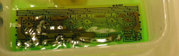
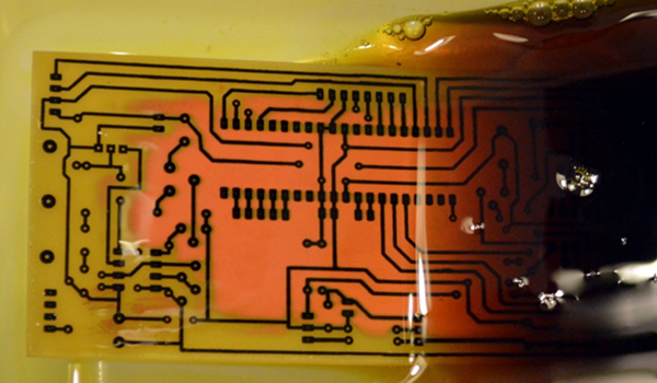
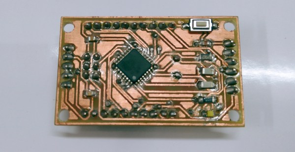
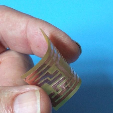
[Pratik Makwana] starts by showing how to design the circuit schematic diagram in an EDA tool (Eagle) and the corresponding PCB layout design. He then uses the toner transfer method and a laminator to imprint the circuit into the copper board for later etching and drilling. The challenging soldering process is not detailed, if you need some help soldering SMD sized components we covered some different processes before, from a toaster oven to a drag soldering process with Kapton tape.

Last but not least, the bootloader firmware. This was done using an Arduino UNO working as master and the newly created the Arduino Nano clone as target. After that you’re set to go. To run an actual sketch, just use your standard USB to UART converter to burn it and proceed as usual.

Voilá, from zero to Nano:

Continue reading “From Zero To Nano”

Christmas Lights Done The Hard Way

It’s that time of the year again when you gotta start worrying if you’ve been naughty enough to not receive any gifts. Hopefully, Blinky Lights will appease St. Nick. Grab a strip of RGB LEDs, hook them up to an Arduino and a Power supply, slap on some code, and Bob’s your Uncle. But if you want to retain your hacker cred, you best do it the hard way. Which is what [roddersblog] did while building his Christmas Starburst LED Stars this year — and bonus points for being early to the party.

christmas-lights-the-hard-way
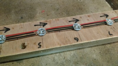
For starters, he got panels (as in PCB panels) of WS2812 boards from eBay. The advantage is it lets you choose your own pitch and strand length. The flip side is, you need to de-panel each board, mount it in a jig, and then solder three lengths of hook up wire to each LED. He planned for an eight sided star with ten LED’s each. And he built three of them. So the wiring was, substantial, to say the least. And he had to deal with silicone sealant that refused to cure and harden. But nothing that some grit and determination couldn’t fix.

For control, he choose the PIC16F1509 microcontroller. This family has a feature that PIC calls the “Configurable Logic Cell” and this Application Note describes how to use CLC to interface the PIC to a WS2811. He noticed processing delays due to C code overheads that caused him some grief. After some experimentation, he re-wrote the entire program in assembly which produced satisfactory results. You can check out his code on the GitHub repository.

Also well worth a look, he’s got a few tricks up his sleeve to improve the quality of his home-brew PCB’s. He’s built his own UV exposure unit with timer, which is an interesting project in itself. The layout is designed in Eagle, with a flood fill to minimize the amount of copper required to be etched away. He takes a laser print of the layout, applies vegetable oil to the paper to make it more translucent to UV, and doubles up the prints to get a nice contrast.

Once the sensitized board has been exposed in the UV unit, he uses a weak but fresh and warm solution of Sodium Hydroxide as a developer to remove the unexposed UV photo-resist. To etch the board, he uses standard Feric Chloride solution, which is kept warm using an aquarium heater, while an aquarium air-pump is used to agitate the solution. He also describes how he fabricates double sided boards using the same technique. The end result is quite satisfying – check out the video after the break.

Continue reading “Christmas Lights Done The Hard Way”

A Stack Of Boards For An Edison Breadboard Adapter

The Intel Edison is a neat piece of hardware, but the connector for the Edison is extremely intimidating and the Mini breakout board is incompatible with breadboards. What’s [Federico], a builder of Internet of Things to do? Etch their own breakout board.

The Mini Breakout board for the Intel Edison is the official ‘minimal’ offering for getting the Edison up and running with a mess of jumper wires and LEDs. While this breakout board handles the USB to UART bridge, power regulation, and exposes all the pins on the Edison connector, it is terrible for prototyping. It’s a 4×14 array of holes on a 0.1″ grid that are hidden underneath the Edison.

[Federico] handled this problem with a copper clad board and a little bit of ferric chloride. He jumped into Eagle and created a breakout board to turn the 4×14 pin grid into a more sensible breadboard-friendly layout.

The breadboard-friendly adapter doesn’t have level shifters, but by using the mini-breakout board between the Edison and the breadboard adapter [Federico] still has the UART to USB hardware and a battery charging circuit. Still, there’s room for improvement and we can’t wait to see what he comes up with next.

Make Flexible PCBs With Your 3D Printer

The last few years have seen great strides in budget printed circuit board manufacturing. These days you can have boards made in a week for only a few dollars a square inch. Flexible PCBs still tend to be rather expensive though. [Mikey77] is changing that by making flex circuits at home with his 3D printer. [Mikey77] utilized one of the properties of Ninjaflex Thermoplastic Elastomer (TPE) filament – it sticks to bare copper!

The TPE filament acts as an etch resist, similar to methods using laser printer toner. For a substrate, [Mikey77] lists 3 options:

.004″ thick “Scissor cut” copper clad board from Electronics Goldmine

.002″ thick pure copper polyester taffeta fabric from lessEMF.com

<.001″ Pyralux material from Adafruit, which is one of the materials used to make professional flex PCBs.

A bit of spray adhesive will hold the Flex PCB down on the printer’s bed. The only issue is convincing the printer to print a few thousandths of an inch higher than the actual bed level. Rather than change the home position on his Z axis, [Mikey77] used AutoDesk 123D to create 3D PCB designs. Each of his .stl files has a “spacer bar”, which sits at the bed level. The actual tracks to be printed are in the air a few thousandths of an inch above the bed – exactly the thickness of the substrate material. The printer prints the spacer bar on the bed, then raises its Z height and prints on the flexible PCB material. We’re sure that forcing the printer to print in mid-air like this would cause some printer software to throw errors, but the system worked for [Mikey77] and his Makerbot.

Once the designs have been printed, the boards are etched with standard etching solutions such as ferric chloride. Be careful though – these thin substrates can etch much faster than regular PCB.

Testing The Efficiency Of PCB Etchants

etchIn the interest of the scientific method [Feynmaniac] (great name, btw) over on Instructables has posted a little experiment on something we all, no doubt, care about: putting PCB traces in copper clad boards with the most common etchants out there.

The experiment used the ‘ol standard, ferric chloride, and the safe, inexpensive newcomer, vinegar, hydrogen peroxide, and table salt. Finding the most efficient mixture of ferric chloride is easy: just use what’s in the bottle. The vinegar and H2O2 requires some stoichiometry, though, and [Feynmaniac] calculated that with an 8% acetic acid solution and the most commonly available 3% peroxide solution, a 2:3 ratio of peroxide to vinegar is the best. Salt to taste, or until everything turns green.

Four copper clad boards were used for the test, masked off in a ‘barcode’ pattern. Two methods of applying the etchant were used: either rubbing the etchant on with a sponge, or immersing the boards in a bath of the etchant being tested.

In terms of speed, ferric chloride was by far the fastest, with 3 minutes until the board was etched using the rubbing method, or 10 minutes when simply immersed. Vinegar/peroxide took longer with 11 minutes rubbed, and 20 minutes immersed. No differences in the quality of the etch were noticed.

While ferric chloride was by far the fastest etchant, it does have the downside of being environmentally unfriendly and fairly expensive. The vinegar and peroxide etchant is safe, cheap, and can be found in any grocery store on the planet.

This experiment didn’t test other common etchants like HCl and H202, or cupric chloride (which is is the byproduct of HCl and H202). Still, it’s a good confirmation that the vinegar and peroxide method actually works, in case you were wondering.