3D Printer Time Lapse Videos Ditch The Blur

Example output of Octolapse with the print head absent from the images.

Most time-lapse videos of 3D prints show a steadily growing print with a crazy blur of machine movement everywhere else. This is because an image is captured at a regular time interval, regardless of what’s physically going on with the machine. But what if images were captured at consistent machine positions instead? [FormerLurker]’s Octolapse plugin for OctoPrint came out of beta recently and does exactly that, and the results are striking. Because OctoPrint knows where a 3D printer’s print head is at all times, it’s possible for a plugin to use this information to create time-lapse videos where the print head position is consistent instead of a crazy blur, or even have the print head absent from the shot altogether.

[FormerLurker] had originally created stabilized time lapses by hand editing G-code, which had great results but was inefficient and time-consuming. This plugin is the result of his work at automating and enhancing the process, and is also his first serious open source programming project. We’ve covered upgrading a 3D printer with OctoPrint before, and the plugins functionality of OctoPrint means features can be added independently from the core system, which itself largely remains a one-woman effort by creator and maintainer [Gina Häußge].


Guide: Why Etch A PCB When You Can Mill?

I recall the point I started taking electronics seriously, although excited, a sense of dread followed upon the thought of facing the two main obstacles faced by hobbyists and even professionals: Fabricating you own PCB’s and fiddling with the ever decreasing surface mount footprints. Any resistance to the latter proves futile, expensive, and frankly a bit silly in retrospect. Cheap SMD tools have made it extremely easy to store, place, and solder all things SMD.

Once you’ve restricted all your hobbyist designs/experiments to SMD, how do you go about producing the PCBs needed for prototyping? Personally, I dread the thought of etching my own boards. The process is laborious and involves messy chemicals and specially sensitized PCB’s — none of which interest me. I’ve only ever done it a few times, and have promised myself never to do it again. Professional but cheap PCB manufacturing is more like it board pooling services such as OSH park have made this both easy and affordable — if you can wait for the turnaround.

So what are the alternatives? If you are really serious about swift prototyping from your own Lab, I put forth the case of milling your own PCB’s. Read on as I take you through the typical workflow from design to prototype and convince you to put up with the relatively high start up cost of purchasing a PCB mill.

Continue reading “Guide: Why Etch A PCB When You Can Mill?”

We Can Now 3D Print Slinkys

A mark of a good 3D print — and a good 3D printer — is interlayer adhesion. If the layers of a 3D print are too far apart, you get a weak print that doesn’t look good. This print has no interlayer adhesion. It’s a 3D printed Slinky, the kind that rolls down stairs, alone or in pairs, and makes a slinkity sound. Conventional wisdom says you can’t print a Slinky, but that didn’t stop [mpclauser] from trying and succeeding.

This Slinky model was made using a few lines of JavaScript that output a Gcode file. There is no .STL file, and you can’t edit this CNC Slinky in any CAD tools. This is also exceptionally weird Gcode. According to [mpclauser], the printer, ‘zigzags’ between an inner and outer radius while constantly increasing the height. This is the toolpath you would expect from a 3D printed Slinky, but it also means the usual Gcode viewers throw a fit when trying to figure out how to display this thing.

All the code to generate your own 3D printable Slinky Gcode file is up on [mpclauser]’s Google Drive. The only way to see this print in action is to download the Gcode file and print it out. Get to it.

DIY 3D Slicer Is A Dynamo

We all know that hacker that won’t use a regular compiler. If he’s not using assembly language, he uses a compiler he wrote. If you don’t know him, maybe it is you! If you really don’t know one, then meet these two. [Nathan Fuller] and [Andy Baldwin] want to encourage you to write your own 3D slicer.

Their post is very detailed and uses Autodesk Dynamo as a graphical programming language. However, the details aren’t really specific to Dynamo. It is like a compiler. You sort of know what it must be doing, but until you’ve seen one taken apart, there are a lot of subtleties you probably wouldn’t think of right away if you were building one from scratch.

Continue reading “DIY 3D Slicer Is A Dynamo”

Zeroing CNC Mills With OpenCV

For [Jay] and [Ricardo]’s final project for [Dr. Bruce Land]’s ECE4760 course at Cornell, they tackled a problem that is the bane of all machinists. Their project finds the XY zero of a part in a CNC machine using computer vision, vastly reducing the time it take to set up a workpiece and giving us yet another reason to water down the phrase ‘Internet of Things’ by calling this the Internet of CNC Machines.

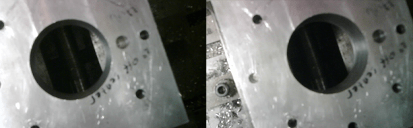
For the hardware, [Jay] and [Ricardo] used a PIC32 to interface with an Arducam module, a WiFi module, and an inductive sensor for measuring the distance to the workpiece. All of this was brought together on a PCB specifically designed to be single-sided (smart!), and tucked away in an enclosure that can be easily attached to the spindle of a CNC mill. This contraption looks down on a workpiece and uses OpenCV to find the center of a hole in a fixture. When the center is found, the mill is zeroed on its XY axis.

The software is a bit simpler than a device that has OpenCV processing running on a microcontroller. Detecting the center of the bore, for instance, happens on a laptop running a few Python scripts. The mill attachment communicates with the laptop over WiFi, and sends a few images of the downward-facing camera over to the laptop. From there, the laptop detects the center of the bore in the fixture plate and generates some G-code to send over to the mill.

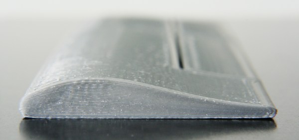
While the device works remarkably well, and is able to center the mill fairly quickly and without a lot of user intervention, there were a few problems. The camera is not perfectly aligned with the axis of the spindle, making the math harder than it should be. Also, the enclosure isn’t rated for being an environment where coolant is sprayed everywhere. Those are small quibbles, and these problems could be fixed simply by designing and printing another enclosure. The device works, though, and really cuts down on the time it takes to zero out a mill.

You can check out the video description of the build below.

Continue reading “Zeroing CNC Mills With OpenCV”

3D Printering: Non-Planar Layer FDM

Non-planar layer Fused Deposition Modeling (FDM) is any form of fused deposition modeling where the 3D printed layers aren’t flat or of uniform thickness. For example, if you’re using mesh bed leveling on your 3D printer, you are already using non-planar layer FDM. But why stop at compensating for curved build plates? Non-planar layer FDM has more applications and there are quite a few projects out there exploring the possibilities. In this article, we are going to have a look at what the trick yields for us.

Continue reading “3D Printering: Non-Planar Layer FDM”

‘LinuxCNC-Features’ Is The Garage-Fab’s Missing CAM Tool

It takes a long toolchain to take the garage-machinist-to-be through all the hoops needed to start cranking out parts. From the choice of CAD software to the CAM tools that turn 3D models into gcode, to the gcode interpretters that chew up this source code and spit out step and direction pulses to turn the cranks of a cnc mill, there’s a multitude of open-and-closed source tools to choose from and even an opportunity to develop some of our own. That’s exactly what [Nick] and the folks over on the cnc-club forums did; they’ve written their own CAM tool that enables the end user to design a procedure of cuts and toolpaths that can export to gcode compatible with LinuxCNC.

Their tool, dubbed “LinuxCNC-features”, embeds a LinuxCNC-compatible graphical gcode programming interface directly into the LinuxCNC native user interface. Creating a part is a matter of defining a list of sequential cuts along programmable toolpaths. These sequential cuts are treatments like drilled holes, square pockets, bolt holes, and lines. The native embedding enables the machinist to preview each of the 3D toolpaths in LinuxCNC’s live view, giving him-or-her a quick-and-dirty check to make sure that their gcode performs as expected before running it. [Nick] has a couple of videos to get you up-and running on either your mill or lathe.

LinuxCNC-features has been out in the wild for almost two years now, but if you’re looking to get started cranking out parts in the garage, look no further for a CAM tool that can quickly generate gcode for simple projects. In case you’re not familiar with LinuxCNC, it’s one of the most mature open-source gcode interpreters designed to turn your PC into a CNC controller, and it’s the brains behind some outstanding DIY CNC machines like this plasma cutter.

Continue reading “‘LinuxCNC-Features’ Is The Garage-Fab’s Missing CAM Tool”