3D Printed Gear Serves Seven Months Hard Labor

Even the staunchest 3D printing supporter would have to concede that in general, the greatest strength of 3D printing is not in the production of final parts, but in prototyping. Sure you can make functional prints, as the pages of this site will attest; but few would argue that you wouldn’t be better off getting your design cut out of metal or injection molded if you planned on putting the part into service over the long term. Especially if the part was to be subjected to rough service in an industrial setting.

While that’s valid advice, it certainly isn’t the definitive word on the issue. Just because a part is printed in plastic on a desktop 3D printer doesn’t necessarily mean it can’t be put into real service, at least for as long as it takes to get proper replacement parts. A recent success story from [bloomautomatic] serves as a perfect example, when one of the gears in his MIG welder split, he decided to try and print up a replacement in PLA while he waited for the nylon gear to get shipped out to him. Fast forward seven months and approximately 80,000 welds later, and [bloomautomatic] reports it’s finally time to install those replacement gears he ordered.

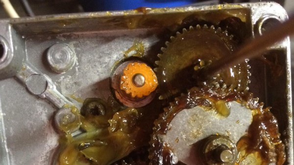
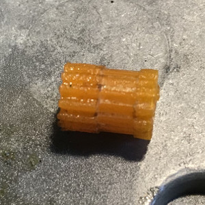
In the pictures [bloomautomatic] posted you can see the printed gear finally wore down to the point the teeth were essentially gone where they meshed with their metal counterparts. To those wondering why the gear was plastic to begin with, [bloomautomatic] explains that it’s intended to be a sacrificial gear that will give way instead of destroying the entire gearbox in the event of a jam. According to the original post he made when he installed the replacement gear, the part was printed in Folgertech PLA on a Monoprice Select Mini. There’s no mention of infill percentage, but with such a small part most slicers would likely have made it essentially solid to begin with.

While surviving seven tortuous months inside of the welder is no small feat, we wonder if hardier PLA formulationstreatment of the part post-printing, or even casting it in a different material couldn’t have turned this temporary part into a permanent replacement.

Network Analysers: The Electrical Kind

Instrumentation has progressed by leaps and bounds in the last few years, however, the fundamental analysis techniques that are the foundation of modern-day equipment remain the same. A network analyzer is an instrument that allows us to characterize RF networks such as filters, mixers, antennas and even new materials for microwave electronics such as ceramic capacitors and resonators in the gigahertz range. In this write-up, I discuss network analyzers in brief and how the DIY movement has helped bring down the cost of such devices. I will also share some existing projects that may help you build your own along with some use cases where a network analyzer may be employed. Let’s dive right in.

Network Analysis Fundamentals

As a conceptual model, think of light hitting a lens and most of it going through but part of it getting reflected back.

The same applies to an electrical/RF network where the RF energy that is launched into the device may be attenuated a bit, transmitted to an extent and some of it reflected back. This analysis gives us an attenuation coefficient and a reflection coefficient which explains the behavior of the device under test (DUT).

Of course, this may not be enough and we may also require information about the phase relationship between the signals. Such instruments are termed Vector Network Analysers and are helpful in measuring the scattering parameters or S-Parameters of a DUT.

The scattering matrix links the incident waves a1, a2 to the outgoing waves b1, b2 according to the following linear equation: \begin{bmatrix} b_1 \\ b_2 \end{bmatrix} = \begin{bmatrix} S_{11} & S_{12} \\ S_{21} & S_{22} \end{bmatrix} * \begin{bmatrix} a_1 \\ a_2 \end{bmatrix} .

The equation shows that the S-parameters are expressed as the matrix S, where and denote the output and input port numbers of the DUT.

This completely characterizes a network for attenuation, reflection as well as insertion loss. S-Parameters are explained more in details in Electromagnetic Field Theory and Transmission Line Theory but suffice to say that these measurements will be used to deduce the properties of the DUT and generate a mathematical model for the same.

General Architecture

As mentioned previously, a simple network analyzer would be a signal generator connected and a spectrum analyzer combined to work together. The signal generator would be configured to output a signal of a known frequency and the spectrum analyzer would be used to detect the signal at the other end. Then the frequency would be changed to another and the process repeats such that the system sweeps a range of frequencies and the output can be tabulated or plotted on a graph. In order to get reflected power, a microwave component such as a magic-T or directional couplers, however, all of this is usually inbuilt into modern-day VNAs.
Continue reading “Network Analysers: The Electrical Kind”

Steampunk-Inspired Art Clock!

Getting paid to do what you enjoy is a special treat. A machinist and fabricator by trade — hobbyist hacker by design — [spdltd] was commissioned to build a mechanical art installation with a steampunk twist. Having complete creative control, he convinced his client to let him make something useful: a giant electro-mechanical clock.

Pieced together from copper, brass, steel, aluminium, and stainless steel, this outlandish design uses an Arduino Yun — a combination Linux and Arduino microcontroller board — to control the stepper motor and query the internet for the local time. Upon boot, the clock auto-calibrates by rotating the clock face until a sensor detects an extra peg and uses that to zero on twelve o’clock; the Yun then grabs the local time over the WiFi and sends the stepper motor a-spinning ’till the correct time is displayed.

At first glance, you may find it hard to get an accurate read of what time it is, but an accent piece’s pegs denote the quarter hour once it lines up with the notch above each hour. At least this one doesn’t require you to match colours or do much math to check the time.

Continue reading “Steampunk-Inspired Art Clock!”

Have Chainsaw, Will Travel

What’s the worst thing that could happen if you strapped a chainsaw motor to a tricycle? Turns out the worst that happened to [ThisDustin] and his friends is that it turned out hilariously awesome.

This aptly-named ‘chainsawtrike’ isn’t much in the way of comfort, so a pair of foot pegs had to be welded onto the front forks, along with a mount for the chainsaw motor. The rear axle had to be replaced with 5/8″ keyed stock, trimmed to fit the trike wheel and secured with keyed hubs. [ThisDustin] and crew also needed an intermediate sprocket to act as a reduction gear.

After a test that saw the chain jump off the sprockets and working out a few kinks — like the ability to turn — the chainsawtrike  can haul around its rider at a pretty decent clip. Check out the video of it in action after the break.

Continue reading “Have Chainsaw, Will Travel”

Path To Craftsmanship: Don’t Buy Awful Safety Gear

A while back I tried to make a case for good safety disciple as a habit that, when proactively pursued, can actually increase the quality of your work as a side effect. In those comments and in other comments since then I’ve noticed that some people really hate safety gear. Now some of them hated them for a philosophical reason, “Ma granpap didn’t need ’em, an’ I don’t neither”, or ,”Safety gear be contributin’ to the wuss’ness of the modern personage an’ the decline o’ society.” However, others really just found them terribly uncomfortable and restricting.

In this regard I can help a little. I’ve spent thousands of terrible long hours in safety gear working in the chemical industry. I was also fortunate to have a company who frequently searched for the best safety equipment as part of their regular program. I got to try out a lot.

Continue reading “Path To Craftsmanship: Don’t Buy Awful Safety Gear”

Improving 3D Printed Gears With… Hot Water

Being able to print out custom gears is one area where 3D printing can really shine, and [Karl Lew] has been busy doing exactly that with pinion gears printed in PLA and mounted to stepper motor shafts, but there are tradeoffs. Pinion gears need to grip a motor shaft tightly – normally done with a screw through the gear and onto the motor shaft. But a motor and its shaft can get quite warm when doing a lot of work, and a tight screw on a hot motor’s shaft will transmit that heat into the PLA, which can then deform.

[Karl Lew] managed to improve things in an unusual way: using a hot water bath to anneal the gear while it is attached to the stepper shaft. Annealing PLA has the effect of increasing the crystallinity of the material, which – according to an article going into some detail about the process of annealing PLA – increases stiffness, strength, and heat deflection. The annealing process also shrinks the part slightly, which happens to result in a very tight joint made between the gear and the slotted stepper shaft if the gear is annealed while connected to the motor.

Continue reading “Improving 3D Printed Gears With… Hot Water”

Laser-cut Cardboard Planetary Gearset Is Pretty, But Useless

[Shane] made a project that speaks directly to our heart — combining laser cutting, cardboard, and gears. How could it be any better? Well, it could do anything. But that’s quibbling. It’s fun enough just to watch the laser-cut cardboard planetary gears turn. (Video after the break.)

It was made on a laser cutter using the gear extensions for generating gears in Inkscape, everybody’s favorite free SVG editor.

In his writeup, [Shane] touches on all of the relevant details: all of the gear pitches need to be the same, and the number of teeth in the sun gear (in the center) needs to equal the number of teeth in the ring (outside) divided by the number of planets (orbiting, in the middle). So far so good.

Continue reading “Laser-cut Cardboard Planetary Gearset Is Pretty, But Useless”