Fail Of The Week : Measuring DC Current Has To Be Easy, Right?

[DainBramage] needed a DC ammeter to check how long his amateur radio station would be able to stay powered on battery backup power. The one’s he already had on hand were a Clamp Meter, which could only measure AC, and another one that measured just a few milliamps. Since he didn’t have one which could measure up to 25A, he decided to build his own DIY DC Ammeter with parts scavenged from his parts bin. Measuring DC current is not too difficult. Pass the current to be measured through a precision resistor, and measure the voltage drop across it using a sensitive voltmeter.

I = V/R

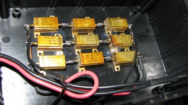
So far, so good. If it’s late at night and you’ve had a lot of coffee, busy building your DC ammeter, things could head south soon. [DainBramage]’s first step was to build a suitable Shunt. He had a lot of old, 1Ω, 10W resistors lying around. He made a series-parallel combination using nine of them to create a hefty 1Ω, 90W shunt (well, 0.999999999 Ohms if you want to be picky). This gave him a nice 1 Volt per Amp ratio, making it easy to do his measurements.

Next step was to hook up the shunt to a suitable voltmeter. Luckily, he had a Micronta voltmeter lying around, ripped out from a Radio Shack product. Since he didn’t have the voltmeter data, he hooked up a 10k resistor across the meter inputs, and slowly increased the voltage applied to the meter. At 260mV, the needle touched full-scale and the voltage across the inputs of the voltmeter was 33mV. [DainBramage] then describes the math he used to calculate the resistors he would need to have a 10A and a 25A measurement range. He misses his chance to catch the fail. His project log then describes some of the boring details of putting all this together inside a case and wrapping it all up.

A while later, his updates crop up. First thing he probably realized was that he needed more accurate readings, so he added connectors to allow attaching a more accurate voltmeter instead of the analog Micronta. At this point, he still didn’t catch the fail although it’s staring him straight in the face.

His head scratching moment comes when he tries to connect his home made ammeter in series with the 12V DC power supply to his amateur radio station. Every time he tries to transmit (which is when the Radio is drawing some current), the Radio shuts off.  If you still haven’t spotted the fail, try figuring out how much voltage gets dropped across the 1Ω shunt resistor when the current is 1A and when it is 5A or more.

Hacklet 37 – Nixie Projects

Nothing quite beats the warm glow of a tube. What better way to enjoy that glow than to use it to read numbers? Nixie tubes were created by Haydu Brothers Laboratories, and popularized by Burroughs Corp in 1955. The name comes from NIX I – or “Numeric Indicator eXperimental No. 1”. By the mid 1970’s, seven segment LED’s were becoming popular and low-cost alternatives to Nixies, but they didn’t have the same appeal. Nixie tubes were manufactured all the way into the 1990’s. There’s just something about that tube glow that hackers, makers, and humans in general love. This week’s Hacklet highlights the best Nixie (and Nixie inspired) projects on Hackaday.io!

temperatureDisplayWe start with [Sascha Grant] and Nixie Temperature Display. [Sascha] mixed an Arduino, a Dallas DS18B20 Temperature sensor, and three IN-12A Nixie tubes to create a simple three digit temperature display. We really love the understated laser-cut black acrylic case. An Arduino Pro Micro reads the Dallas 1-wire sensor and converts the temperature to BCD. High voltage duties are handled by a modular HV power supply which bumps 9V up to the required 170V.  Controlling the Nixie tubes themselves are the classic K155ID1 BCD to decimal converter chips – a favorite for clock builders.


driverNext up is [Christoph] with Reading Datasheets and Driving Nixie Tubes. Chips like the K155ID1, and the 74141 make driving Nixie tubes easy. They convert Binary Coded Decimal (BCD) to discrete outputs to drive the cathodes of the Nixie. More importantly, the output drivers of this chip are designed to handle the high voltages involved in driving Nixie tubes. These chips aren’t manufactured anymore though, and are becoming rare. [Christoph] used more common parts. His final drive transistor is a MPSA42 high voltage NPN unit. Driving the MPSA42’s is a 74HC595 style shift register. [Christoph] used a somewhat exotic Texas Instruments TPIC6B595 with FET outputs, but any shift register should work here. The project runs on a Stellaris Launchpad, so it should be Arduino compatible code.

fixietube[Davedarko] has the fixietube clock. Fixietube isn’t exactly a Nixie. It’s an LED based display inspired by Nixie tubes. Modern amber LEDs aren’t quite the same as classic Nixies, but they get pretty darn close. [Dave] designed a PCB with a 3×5 matrix of LEDs to display digits. A few blue LEDs add a bit of ambient light. The LEDs are driven with a 74HC595 shift register. The entire assembly mounts inside a tiny glass jam jar, giving it the effect of being a vacuum tube. The results speak for themselves – fixietubes certainly aren’t Nixies, but they look pretty darn good. Add a nice 3D printed case, and you’ve got a great project which is safe for anyone to build.

openNixieFinally, we have [Johnny.drazzi] with his Open Nixie Clock Display. [Johnny] has been working on Open Nixie for a few years. The goal is to create a Nixie based clock display which can be driven over the SPI bus. So far, [Johnny] has 6 Russian IN-12 tubes glowing with the help of the ubiquitous K155ID1 BCD to decimal converter. The colons of the clock are created with two INS-1 neon indicators. [Johnny] spends a lot of time analyzing the characteristics of a Nixie tube – including the strike voltage, and steady state current. If you’re interested in building a Nixie circuit yourself, his research is well worth a read!

Not satisfied? Want more Nixie goodness? Check out our Nixie tube project list!

That’s about all the time we have for this week’s Hacklet. As always, see you next week. Same hack time, same hack channel, bringing you the best of Hackaday.io!

DIY Thermal Insert Press

You might not know what a threaded insert is, but chances are you’ve seen one before. Threaded inserts are small metal (typically brass) inserts that are pressed into plastic to give a strong point of attachment for bolts and screws. These inserts are a huge step up from screwing or bolting directly into tapped plastic holes since the brass threads are very strong compared to the plastic. The only major downside to these inserts is that the press to install them is incredibly expensive. Thankfully, [Alex Rich] came up with a cheap solution: a modified soldering iron mounted to an Arbor press.

Commercial threaded insert presses typically use ultrasonic welding or heat welding to fuse inserts with plastic. [Alex] chose the simple route and went with heat welding, which (as you might imagine) is way simpler than ultrasonic welding. To provide the heat, [Alex] mounted a 100W Weller soldering iron to the press, which he says handles the impact with no problem. Unfortunately the copper tips of the Weller just wouldn’t hold up to the impact, so [Alex] made his own tips out of some brass he turned on a lathe.

If, like most people, you don’t have the capability of making injection-molded cases, let alone an Arbor press on hand, you’re not out of luck! Using this same technique people have successfully added thermal inserts to 3d-printed parts using a soldering iron and much smaller DIY presses. Have any ideas on how you could use thermal inserts in your 3d prints? Let us know in the comments.

BeagleSNES For Game Boy, Game Boy Advance, NES, And – Yes – SNES

By far the most common use for the Raspberry Pi is shoving a few dozen emulators on an SD card and calling it a day. Everybody’s got to start somewhere, right? There are other tiny, credit card-sized Linux boards out there, and [Andrew] is bringing the same functionality of the Raspi to the BeagleBone Black and BeagleBoard with BeagleSNES, an emulator for all the sane pre-N64 consoles.

BeagleSNES started as a class project in embedded system design, but the performance of simply porting SNES9X wasn’t very good by default. [Andrew] ended up hacking the bootloader and kernel, profiling the emulator, and slowly over the course of three years of development making this the best emulator possible.

After a few months of development, [Andrew] recently released a new version of BeagleSNES that includes OpenGL ES, native gamepad support through the BeagleBone’s PRU, and support for all the older Nintendo consoles and portables. Video demos below.

Continue reading “BeagleSNES For Game Boy, Game Boy Advance, NES, And – Yes – SNES”

Hackaday Links Column Banner

Hackaday Links: March 1, 2015

The somewhat regular Hardware Developers Didactic Galactic was a few days ago in San Francisco. Here’s the video to prove it. Highlights include [James Whong] from Moooshimeter, the two-input multimeter, [Mark Garrison] from Saleae, and a half-dozen other people giving talks on how to develop hardware.

[Taylor] made a portable NES with a retron, a new-ish NES clone that somehow fits entirely in a glop top IC. The controllers sucked, but [Taylor] made a new one with touch sensors. All that was required was eight transistors. The enclosure is an Altoid tin, and everything works great.

Here’s a YouTube channel you should subscribe to: Ham College. The latest episode covers the history of radio receivers and a crystal radio demonstration. They’re also going through some of the Technical class question pool, providing the answers and justification for those answers.

[Prusa] just relaunched prusaprinters and he’s churning out new content for it. Up now is an interview with [Rick Nidata] and his awesome printed container ship.

The tip line is overflowing with ESP8266 breakout boards. Here’s the simplest one of them all. It’s a breadboard adapter with stickers on the pin headers. Turn that into a right-angle breadboard adapter, and you’ll really have something.

Here’s something that’s a bit old, but still great. [Dillon Markey], one of the stop-motion animators for Robot Chicken modified a Nintendo Power Glove for animation duties. It seems to work great, despite being so bad. Thanks [Nicholas] for the link.

[David] the Swede – a consummate remote control professional we’ve seen a few times before – just flew his tricopter in a mall so dead it has its own Wikipedia page. Awesome tricopter, awesome location, awesome video, although we have to wonder how a few really, really bright LEDs would make this video look.

Here’s an item from the tip line. [Mark] wrote in with an email, “Why do you put names in [square brackets] in the blog entries? Just curious.” The official, [Caleb]-era answer to that question is that sometimes people have bizarre names that just don’t work in text. Imagine the sentence, “[12VDC] connected the wires to the terminal” without brackets. The semi-official answer I give is, “because.”

Raspberry Pi GSM Hat

The Spark Electron was released a few days ago, giving anyone with the Arduino IDE the ability to send data out over a GSM network. Of course, the Electron is just a GSM module tied to a microcontroller, and you can do the same thing with a Pi, some components, and a bit of wire.

The build is fairly basic – just an Adafruit Fona, a 2000 mah LiPo battery, a charge controller, and a fancy Hackaday Perma-Proto Hat, although a piece of perf board would work just as well in the case of the perma-proto board. Connections were as simple as power, ground, TX and RX. With a few libraries, you can access a Pi over the Internet anywhere that has cell service, or send data from the Pi without a WiFi connection.

If you decide to replicate this project, be aware you have an option of soldering the Fona module right side up or upside down. The former gives you pretty blinking LEDs, while the latter allows you to access the SIM. Tough choices, indeed.

DSP 01: Real, Legit Audiophile Goodness

About six months ago, we saw [tshen2]’s work on the DSP 01, a 2-input, 6-output DSP and crossover for extreme audiophiles, and we’re not talking about oxygen free rooms here. The DSP 01 turns a USB audio output into six outputs that will give you perfectly flat eq across bass, mids, and highs, integrates with a 6x100W amplifier, and compensates for room noise. There was a huge update to the project recently and [tshen] is more than happy to share the details

Getting to this phase of the project hasn’t been without its problems. To get the DSP communicating to a computer through a USB port, [tshen2] found a potential solution in the CP2114 USB to I2S Bridge. This device should function as a USB audio sink, translating digital audio into something the DSP understands. This chip did not work in [tshen]’s design. The CP2114 simply does I2S wrong; the I2S spec says the clock must be continuous. This chip implements I2S with a SPI, firmware, and a few other things, making it incompatible with to-spec I2S.

While there was some problems with getting audio in to the device, the core of the device has remained unchanged. [tshen2] is still using the Analog Devices DSP, with the interesting SigmaStudio being used to compensate for the frequency response of the room. This real, legit, science-based audiophile territory here, and an impressive development for a field that – sometimes understandably – doesn’t get the respect it deserves.