Lithium-Ion Battery Circuitry Is Simple

By now, we’ve gone through LiIon handling basics and mechanics. When it comes to designing your circuit around a LiIon battery, I believe you could benefit from a cookbook with direct suggestions, too. Here, I’d like to give you a collection of LiIon recipes that worked well for me over the years.

I will be talking about single-series (1sXp) cell configurations, for a simple reason – multiple-series configurations are not something I consider myself as having worked extensively with. The single-series configurations alone will result in a fairly extensive writeup, but for those savvy in LiIon handling, I invite you to share your tips, tricks and observations in the comment section – last time, we had a fair few interesting points brought up!

The Friendly Neighborhood Charger

There’s a whole bunch of ways to charge the cells you’ve just added to your device – a wide variety of charger ICs and other solutions are at your disposal. I’d like to focus on one specific module that I believe it’s important you know more about.

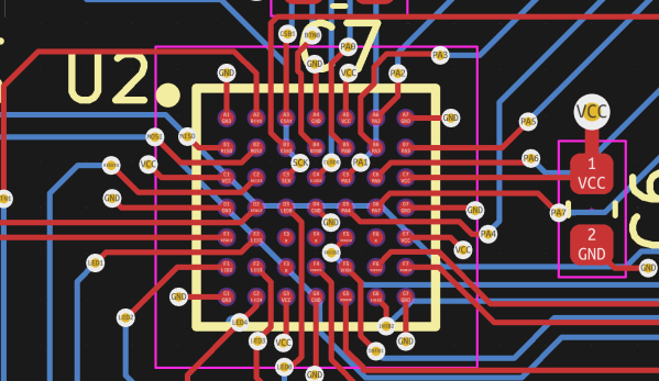
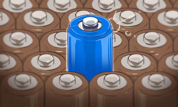
You likely have seen the blue TP4056 boards around – they’re cheap and you’re one Aliexpress order away from owning a bunch, with a dozen boards going for only a few bucks. The TP4056 is a LiIon charger IC able to top up your cells at rate of up to 1 A. Many TP4056 boards have a protection circuit built in, which means that such a board can protect your LiIon cell from the external world, too. This board itself can be treated as a module; for over half a decade now, the PCB footprint has stayed the same, to the point where you can add a TP4056 board footprint onto your own PCBs if you need LiIon charging and protection. I do that a lot – it’s way easier, and even cheaper, than soldering the TP4056 and all its support components. Here’s a KiCad footprint if you’d like to do that too.

Continue reading “Lithium-Ion Battery Circuitry Is Simple”

Lithium-Ion Batteries Are Easy To Find

In the first article, I’ve given you an overview of Lithium-Ion batteries and cells as building blocks for our projects, and described how hackers should treat their Lithium-Ion cells. But what if you don’t have any LiIon cells yet? Where do you get LiIon cells for your project?

Taking laptop batteries apart,  whether the regular 18650 or the modern pouch cell-based ones, remains a good avenue – many hackers take this road and the topic is extensively covered by a number of people. However, a 18650 cell might not fit your project size-wise, and thin batteries haven’t quite flooded the market yet. Let’s see what your options are beyond laptops. Continue reading “Lithium-Ion Batteries Are Easy To Find”

Lithium-Ion Batteries Are Your Friends

Need some kind of battery for a project? You can always find a few Lithium-Ion (LiIon) batteries around! They’re in our phones, laptops, and a myriad other battery-powered things of all forms – as hackers, we will find ourselves working with them more and more. Lithium-Ion batteries are unmatched when it comes to energy capacity, ease of charging, and all the shapes and sizes you can get one in.

There’s also misconceptions about these batteries – bad advice floating around, fearmongering videos of devices ablaze, as well as mundane lack of understanding. Today, I’d like to provide a general overview of how to treat your LiIon batteries properly, making sure they serve you well long-term.

What’s A Battery? A Malleable Pile Of Cells

Lithium-Ion batteries are our friends. Now, there can’t be a proper friendship if you two don’t understand each other. Lithium-Ion batteries are tailored for human needs by the factory that produced them. As for us hackers, we’ll want to learn some things.

First thing to learn – a single LiIon “unit” is called a cell. An average laptop contains three or six Li-Ion cells, a phone will have one, a tablet will have from one to three. What we refer to as “battery” is typically one or multiple cells, together with protection circuitry, casing and a separate connector – most of the time all three of these, but not always. The typical voltage is 3.6 V or 3.7 V, with maximum voltage being 4.2 V – these are chemistry-defined, the same for most kinds of cells and almost always written on the cell. Continue reading “Lithium-Ion Batteries Are Your Friends”

Build Your Own… Whatever

You can read all about making, say, a bookshelf or bowling, but unless you’ve actually done it, you don’t really know how it works. That’s the idea behind [codecrafters-io] Build-Your-Own-X GitHub repository. It is a collection of software projects from around the Web that offer “step-by-step guides for recreating our favorite technologies from scratch.”

What can you find there? Well, how about writing your own version of Git itself? Or maybe you’d like to dive into a physics engine, blockchain code, or a text editor. Then there’s our favorite: an operating system.

Continue reading “Build Your Own… Whatever”

Working With BGAs: Design And Layout

The Ball Grid Array, or BGA package is no longer the exclusive preserve of large, complex chips on computer motherboards: today even simple microcontrollers are available with those little solder balls. Still, many hobbyists prefer to stay with QFP and QFN packages because they’re easier to solder. While that is a fair point, BGA packages can offer significant space savings, and are sometimes the only choice: with the ongoing chip shortage, some other package versions might simply be unavailable. Even soldering doesn’t have to be complicated: if you’re already comfortable with solder paste and reflow profiles, adding a BGA or two into the mix is pretty easy.

In this article we’ll show that working with BGA chips is not as difficult as it may seem. The focus will be on printed circuit board design: how to draw proper footprints, how to route lots of signals and what capabilities your PCB manufacturer should have. We’ll cover soldering and rework techniques in a future article, but first let’s take a look at why BGAs are used at all.

Continue reading “Working With BGAs: Design And Layout”

Electronic Dice Is Introduction To Microcontroller Programming

By now most of us are familiar with the Arduino platform. It’s an inexpensive and fairly easy way into the world of microcontrollers. For plenty of projects, there’s no need to go beyond that unless you have a desire to learn more of the inner workings of microcontrollers in general. [Cristiano] was interested in expanding some of his knowledge, so he decided to build this electronic dice using a PIC microcontroller instead of the Arduino platform he was more familiar with.

As a result, this project is set up as a how-to for others looking to dive further into the world of microcontrollers that don’t have the same hand-holding setup as the Arduino. To take care of the need for a random number for the dice, the PIC’s random number generator is used but with the added randomness of a seed from an internal timer. The timer is started when a mercury tilt switch signals the device that it has been rolled over, and after some computation a single digit number is displayed on a seven-segment display.

While it might seem simple on the surface, the project comes with an in-depth guide on programming the PIC family of microcontrollers, and has a polish not normally seen on beginner projects, including the use of the mercury tilt switch which gives it a retro vibe. For some other tips on how to build projects like this, take a look at this guide on how to build power supplies for your projects as well.

Continue reading “Electronic Dice Is Introduction To Microcontroller Programming”

How To Get Your Diffraction Grating 3D Prints Right The First Time

Diffraction gratings are beautiful things, bending transmitted and reflected light and splitting it into its component wavelengths to create attractive iridescent rainbow patterns. It’s the same effect you see on the bottom of a CD!

You can 3D print a functional diffraction grating, too, with the right techniques, as it turns out! The average 3D printer can’t recreate the tiny-scaled patterns of a diffraction grating directly; a typical diffraction grating may have up to 1000 lines per mm. Instead, by 3D printing onto an existing diffraction grating, the print can pick up the texture on its base layer. It’s a great way to add iridescence and shine to a print.

We’ve seen similar work before, but the guide from [All3DP] goes into greater detail on how to get the effect to work just right. Getting the bed as close to perfectly level is key here, as is the first layer height. This is because the first layer of plastic has to meld perfectly with the diffraction grating to pick up the pattern. Too high and the grooves won’t transfer to the plastic, and too low, and it’s likely you’ll just melt the grating itself. Setting the Z-offset appropriately can help here.

Choosing the right bed temperature is also important to ensure the molten plastic is able to flow into the grooves of the grating. Again, the temperature at which the diffraction grating itself can survive is important to take into account; going above 90 degrees can be risky here. The guide also shows two methods of achieving the goal: one can either use an off-the-shelf grating, or one can prepare a no-longer-wanted CD into a suitable print surface.

Naturally, removing the print must be done delicately, lest one disturb the delicate structures key to generating the iridescent effect. [All3DP] recommends using a freezer to help separate the parts from the grating surface. It also bears noting that the print won’t survive excessive handling, as the grating structures will get damaged by physical touch.

It’s a great in-depth guide on how to get diffraction grating prints right. Meanwhile, consider diving deeper into the world of 3D printed optics!