CNC Toolpath Visualisation With OpenCV

[Tony Liechty] has been having a few issues getting into CNC machining — starting with a simple router, he’s tripped over the usual beginners’ problems, you know, things like alignment of the design to the workpiece shape, axis clipping and workpiece/clamp collisions. He did the decent hacker thing, and turned to some other technologies to help out, and came up with a rather neat way of using machine vision with OpenCV to help preview the toolpath against an image of the workpiece in-situ (video, embedded below.)

ChArUco (a combined chessboard and ArUco marker pattern) boards taped to the machine rails were used to give OpenCV a reference of where points in space are with respect to the pattern field, enabling identification of pixel locations within the image of the rails. A homography transformation is then used to link the two side references to an image of the workpiece. This transformation allows the system to determine the physical location of any pixel from the workpiece image, which can then be overlaid with an image of the desired toolpath. Feedback from the user would then enable adjustment of the path, such as shifts, or rotates to be effected in order to counter any issue that can be seen. The reduction of ‘silly’ clamping, positioning and other such issues, means less time wasted and fewer materials in scrap bin, and that can only be a good thing.

[Tony] says this code and setup is just a demo of the concept, but such ‘rough’ code could well be the start of something great, we shall see. Checkout the realWorldGcodeSender GitHub if you want to play along at home!

We’ve seen a few uses of OpenCV for assisting with CNC applications, like this cool you draw it, i’ll cut it hack, and this method for using machine vision to zero-in a CNC mill onto the centre of a large hole.

Continue reading “CNC Toolpath Visualisation With OpenCV”

Digital Painting On An IPad With Real Brushes

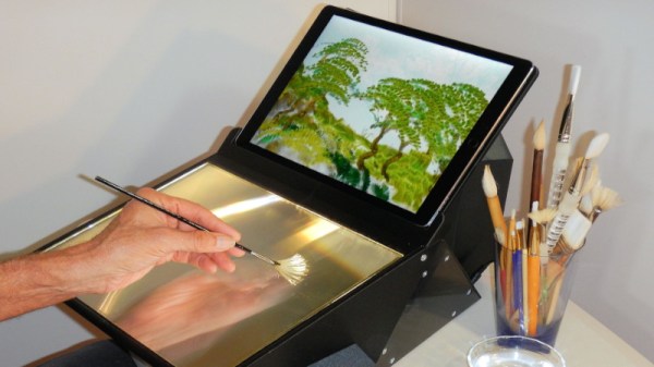
Drawing tablets are a great way to make digital art, and iPads and other tablets are similarly popular in this area. However, they all typically involve using some sort of special stylus for input. [Richard Greene] developed another method, with Light Strokes for the iPad letting one “paint” with real paint brushes instead!

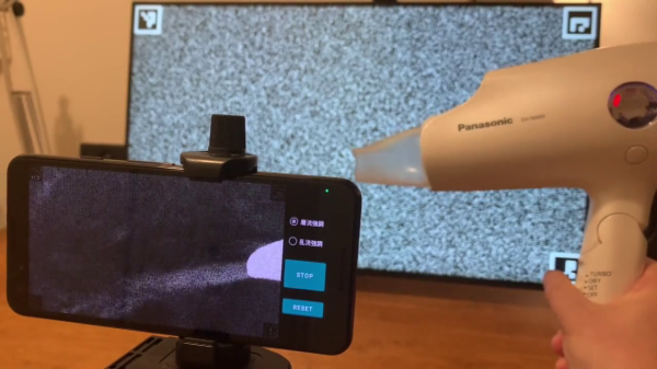
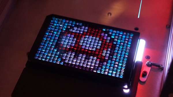
The system uses a Fresnel prism in view of the iPad’s camera. This allows the camera to see only the parts of a paint brush, sponge, or other implement, as they make contact with the surface of the prism itself. This is via the principle known as total internal reflection.

Thus, simply wetting a paintbrush, sponge, or even a finger, allows one to paint quite authentically on the surface of the prism. The corresponding Light Strokes app on the iPad turns this into the pretty pixels of your creation. The app also allows one to experiment with all manner of fancy brush effects, too.

The build requires some finesse, with the lamination of the special Fresnel film onto glass using liquid optically clear adhesive, or LOCA. A series of mirrors are then assembled in an enclosure, allowing the iPad to be mounted with the camera having a good view of the glass painting area.

The project takes advantage of a simple physical effect in order to create a great artistic tool. Alternatively, if you prefer to draw directly, consider whipping up your own screen-based drawing tablet. Video after the break.

Continue reading “Digital Painting On An IPad With Real Brushes”

What Exactly Is A Gaussian Blur?

Blurring is a commonly used visual effect when digitally editing photos and videos. One of the most common blurs used in these fields is the Gaussian blur. You may have used this tool thousands of times without ever giving it greater thought. After all, it does a nice job and does indeed make things blurrier.

Of course, we often like to dig deeper here at Hackaday, so here’s our crash course on what’s going on when you run a Gaussian blur operation. Continue reading “What Exactly Is A Gaussian Blur?”

Liquid Lite Brite Robot

Liquid handling workstations are commonly used in drug development, and look like small CNC machines with droppers on the ends which can dispense liquid into any container in a grid array. They are also extraordinarily expensive, as is most specialty medical research equipment. This liquid handling workstation doesn’t create novel drugs, though, it creates art, and performs similar functions to its professional counterparts at a much lower cost in exchange for a lot of calibration and math.

The art is created by pumping a small amount of CMYK-colored liquids into a 24×16 grid, with each space in the grid able to hold a small amount of the colored liquid. The result looks similar to a Lite-Brite using liquids instead of small pieces of plastic. The creator [Zach Frew] created the robot essentially from scratch using an array of 3D printers, waterjets, and CNC machines. He was able to use less expensive parts, compared to medical-grade equipment, by using servo-controlled valves and peristaltic pumps, but makes up for their inaccuracies with some detailed math and calibration.

The results of the project are striking, especially when considering that a lot of hurdles needed to be cleared to get this kind of quality, including some physical limitations on the way that the liquids behave in the first place. It’s worth checking out not just for the art but for the amount of detail involved as well. And, for those still looking to scratch the 90s nostalgia itch, there are plenty of other projects using the Lite Brite as inspiration.

Thanks to [Thane Hunt] for the tip!

Even More Firmware In Your Firmware

There are many ways to update an embedded system in the field. Images can fly through the air one a time, travel by sneaker or hitch a ride on other passing data. OK, maybe that’s a stretch, but there are certainly a plethora of ways to get those sweet update bytes into a target system. How are those bytes assembled, and what are the tools that do the assembly? This is the problem I needed to solve.

Recall, my system wasn’t a particularly novel one (see the block diagram below). Just a few computers asking each other for an update over some serial busses. I had chosen to bundle the payload firmware images into the binary for the intermediate microcontroller which was to carry out the update process. The additional constraint was that the blending of the three firmware images (one carrier and two payload) needed to happen long after compile time, on a different system with a separate toolchain. There were ultimately two options that fit the bill.

The system thirsty for an update

Continue reading “Even More Firmware In Your Firmware”

Putting The Firmware In Your Firmware

Performing over-the-air updates of devices in the field can be a tricky business. Reliability and recovery is of course key, but even getting the right bits to the right storage sectors can be a challenge. Recently I’ve been working on a project which called for the design of a new pathway to update some small microcontrollers which were decidedly inconvenient.

There are many pieces to a project like this; a bootloader to perform the actual updating, a robust communication protocol, recovery pathways, a file transfer mechanism, and more. What made these micros particularly inconvenient was that they weren’t network-connected themselves, but required a hop through another intermediate controller, which itself was also not connected to the network. Predictably, the otherwise simple “file transfer” step quickly ballooned out into a complex onion of tasks to complete before the rest of the project could continue. As they say, it’s micros all the way down.

The system de jour

Continue reading “Putting The Firmware In Your Firmware”

Schlieren On A Stick

Schlieren imaging is a technique for viewing the density of transparent fluids using a camera and some clever optical setups. Density of a fluid like air might change based on the composition of the air itself with various gasses, or it may vary as a result of a sound or pressure wave. It might sound like you would need a complicated and/or expensive setup in order to view such things, but with a few common things you can have your own Schlieren setup as [elad] demonstrates.

His setup relies on a cell phone, attached to a selfie stick, with a spherical mirror at the other end. The selfie stick makes adjusting the distance from the camera to the mirror easy, as a specific distance from the camera is required as a function of focal length. For cell phone cameras, it’s best to find this distance through experimentation using a small LED as the point source. Once it’s calibrated and working, a circular field of view is displayed on the phone which allows the viewer to see any change in density in front of the mirror.

The only downside of this build that [elad] notes is that the selfie stick isn’t stiff enough to prevent the image from shaking around a little bit, but all things considered this is an excellent project that shows a neat and useful trick in the photography/instrumentation world that could be useful for a lot of other projects. We’ve only seen Schlieren imaging once before and it used a slightly different method of viewing the changing densities.

Continue reading “Schlieren On A Stick”