Unlocking SIM Cards With A Logic Analyzer

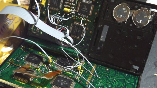
[Jason Gin] wanted to reuse the SIM card that came with a ZTE WF721 wireless terminal he got from AT&T, but as he expected, it was locked to the device. Unfortunately, the terminal has no function to change the PIN and none of the defaults he tried seemed to work. The only thing left to do was crack it open and sniff the PIN with a logic analyzer.

This project is a fantastic example of the kind of reverse engineering you can pull off with even a cheap logic analyzer and a keen eye, but also perfectly illustrates the fact that having physical access to a device largely negates any security measures the manufacturer tries to implement. [Jason] already knew what the SIM unlock command would look like; he just needed to capture the exchange between the WF721 and SIM card, find the correct byte sequence, and look at the bytes directly after it.

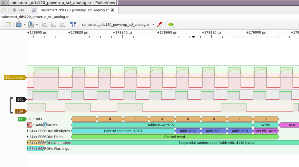
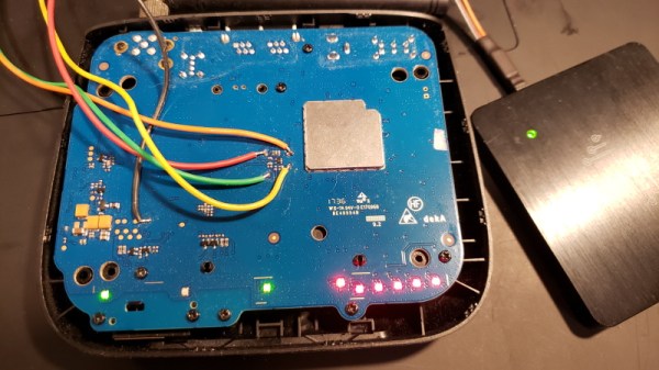
Finding the test pads on the rear of the SIM slot, he wired his DSLogic Plus logic analyzer up to the VCC, CLK, RST, and I/O pins, then found a convenient place to attach his ground wire. After a bit of fiddling, he determined the SIM card was being run at 4 MHz, so he needed to configure a baud rate of 250 kbit/s to read the UART messages passing between the devices.

Once he found the bytes that signified successful unlocking, he was able to work his way backwards and determine the unlock command and its PIN code. It turns out the PIN was even being sent over the wire in plain text, though with the way security is often handled these days, we can’t say it surprises us. All [Jason] had to do then was put the SIM in his phone and punch in the sniffed PIN when prompted.

Could [Jason] have just run out to the store and picked up a prepaid SIM instead of cracking open this wireless terminal and sniffing its communications with a logic analyzer? Of course. But where’s the fun in that?

The Bluetooth LCD Sniffer You Didn’t Know You Needed

At one time or another, we’ve all suffered through working with a piece of equipment that didn’t feature a way to export its data to another device. Whether it was just too old to offer such niceties, or the manufacturer locked the capability behind some upgrade, the pain of staring at digits ticking over on a glowing LCD display and wishing there was a practical way to scrape what our eyes were seeing is well known to hackers.

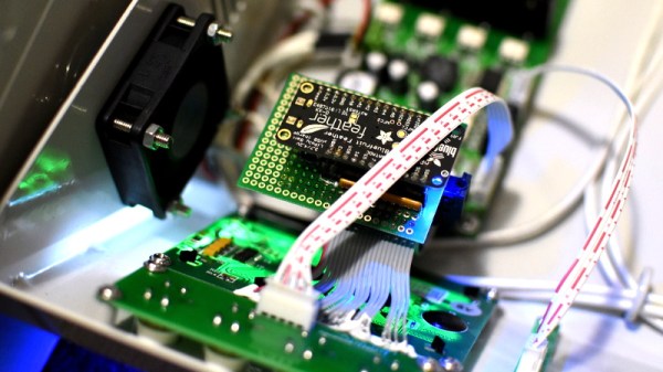
That was precisely the inspiration for DoMSnif, the dot matrix LCD sniffer that [Blecky] has been working on. Originally the project started as a way to record the temperature of his BRTRO-420 reflow oven, but realizing that such a device could have widespread appeal to other hardware hackers, he’s rightfully decided to enter it into the 2019 Hackaday Prize. If perfected, it could be an excellent way to bolt data capture capabilities to your older devices.

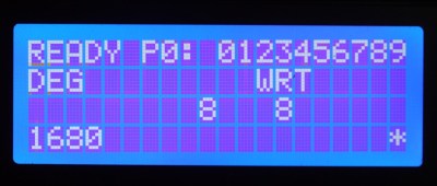
The first phase of this project was figuring out how to capture and parse the signals going into the device’s KS0108 LCD. Getting the data was certainly easy enough, he just had to hook a logic analyzer up between the display and the main board of the device. Of course, figuring out what it all means is a different story.

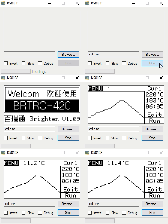
After running the oven for a bit with the analyzer recording, [Blecky] had more than enough data to get started on decoding it. Luckily, the layout of this fairly common 128×64 pixel display is well documented and easy enough to understand. With a little work, he was able to create a tool that would import the captured data and display it on a virtual LCD.

Unfortunately, the Bluetooth part is where things get tricky. Ultimately, [Blecky] wants to ditch the logic analyzer and use a Adafruit Feather nRF52 Bluefruit to capture the signals going to the LCD and pipe them to a waiting device over Bluetooth. But his testing has found that the nRF52’s radio is simply too slow. The display is receiving data every 14us, but it takes the radio at least 50us to send a packet.

[Blecky] is looking at ways around this problem, and we’re confident he’ll crack it. The solution could be in buffering and compressing the data before sending it out, though you’d lose the ability to monitor the display in real-time. Even if he has to abandon the Bluetooth aspect entirely and make the device wired, we still think there would be a market for an easy to use hardware and software solution for scraping LCD data.

A Modular Logic Analyzer For FPGAs

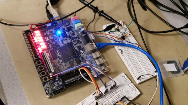
When working on a project, it’s incredibly helpful to be able to visualize the various signals in play. This is important when attempting to determine if what is supposed to be happening is actually happening. However, logic analyzers can be expensive, so a group from [Bruce Land]’s ECE5760 class developed their own hardware solution instead.

The primary idea behind the project is modularity. The basic building blocks of the logic analyser are coded in Verilog. They’re designed so that the number of channels and added functions can be mixed and match to suit the given purpose and the capabilities of the target FPGA platform. The team’s logic analyzer is also capable of decoding SPI and I2C in hardware, and has a graphical user interface running on an attached laptop for visualizing signals.

It’s a tidy build, and an excellent project to learn the fundamentals of both FPGA programming and the various communications protocols involved. [Bruce Land]’s classes are a hotbed of FPGA projects, from pokerbots to NES chiptune emulators. Video after the break.

Continue reading “A Modular Logic Analyzer For FPGAs”

Teardown: AppLights Personalized Projection

Listen, it hurts to hear, but somebody needs to say it. It’s over, OK? You’ve got to admit it and move on. Sure, you could get away with it for a week or two in January, but now it’s just getting weird. No matter how hard you fight it, the facts are the facts: the holidays are over. It’s time to pack up all those lights and decorations before the neighbors really start talking.

Fun Fact: It can’t actually do this

But don’t worry, because there’s an upside. Retailers are now gearing up for their next big selling season, which means right now clearance racks the world over are likely to be playing home to holiday lights and decor. That wouldn’t have been very interesting to the average hacker or maker a few years ago, after all, there’s only so much you can do with a string of twinkle lights. But today, holiday decorations are dripping with the sort of high-tech features you’d expect from gadgets that are actively aiming to be obsolete within the next ten months or so.

Case in point, the “AppLights Personalized Projection” which I found sulking around the clearance section of the Home Depot a couple weeks back. This device advertises the ability to project multi-color custom messages and animations on your wall, and is configured over Bluetooth with a companion application on your Android or iOS device. At a minimum we can assume the device must contain a fairly powerful RGB LED, an LCD to shine the light through, and some sort of Bluetooth-compatible microcontroller. For $20 USD, I thought it was worth taking a shot on.

Around this time last year, the regular Hackaday reader may recall I did a teardown for a Christmas laser projector. Inside we found red, green, and blue lasers of considerable power, as well as all the optics and support hardware to get them running. It was a veritable laser playground for $14. Let’s see if the AppLights projector turns out to be a similar electronic cornucopia, and whether or not we’ve got a new Hackaday Holiday tradition on our hands.

Continue reading “Teardown: AppLights Personalized Projection”

Preserving Floppy Disks Via Logic Analyser

The floppy disk is a technology that is known only to the youth of today as the inspiration for the Save icon. There’s a lot of retro computing history tied up in these fragile platters, thus preservation is key. But how to go about it? [CHZ-Soft] has found an easy way, using a logic analyzer and a healthy dose of Python.

Floppy drives have particularly low-level interfaces, offering up little more than a few signals to indicate the position of the head on the disk, and pulses to indicate changes in magnetic flux. The data is encoded in the pattern of flux changes. This has important implications as far as preservation goes – it’s best to record the flux changes themselves, and create an image of the exact magnetic state of the disk, and then process that later, rather than trying to decode the disk at the time of reading and backing up just the data itself. This gives the best likelihood of decoding the disk and preserving an accurate image of floppy formats as they existed in the real world. It’s also largely platform agnostic – you can record the flux changes, then figure out the format later.

[CHZ-Soft] takes this approach, explaining how to use a Saleae logic analyser and a serial port to control a floppy drive and read out the flux changes on the disk. It’s all controlled automatically through a Python script, which automates the process and stores the results in the Supercard Pro file format, which is supported by a variety of software. This method takes about 14MB to store the magnetic image of a 720KB disk, and can even reveal a fingerprint of the drive used to write the disk, based on factors such as jitter and timing.

It’s an impressive hack that shows that preservation-grade backups of floppy disks can be achieved without spending big money or using specialist hardware. We’ve seen other projects in this space before, too.

X-Ray Vision For FPGAs: Using Verifla

Last time I talked about how I took the open source Verifla logic analyzer and modified it to have some extra features. As promised, this time I want to show it in action, so you can incorporate it into your own designs. The original code didn’t actually capture your data. Instead, it created a Verilog simulation that would produce identical outputs to your FPGA. If you were trying to do some black box simulation, that probably makes sense. I just wanted to view data, so I created a simple C program that generates a VCD file you can read with common tools like gtkwave. It is all on GitHub along with the original files, even though some of those are not updated to match the new code (notably, the PDF document and the examples).

If you have enough pins, of course, you can use an external logic analyzer. If you have enough free space on the FPGA, you could put something like SUMP or SUMP2 in your design which would be very flexible. However, since these analyzers are made to be configurable from the host computer, they probably have a lot of circuitry that will compete with yours for FPGA space. You configure Verifla at compile time which is not as convenient but lets it have a smaller footprint.

Continue reading “X-Ray Vision For FPGAs: Using Verifla”

Logic Analyzers For FPGAs: A Verilog Odyssey

Sometimes you start something simple and then it just leads to a chain reaction of things. I wanted to write a post about doing state machines in Verilog and target the Lattice iCEstick board that we often use for quick FPGA projects. That led to a small problem: how do you show what’s going on inside? In this series of posts, we’ll look at building a logic analyzer into an FPGA to help debug itself, instantiating memory, and — finally — state machines.

Logic analysis is a common tool in FPGA development. If you use Altera, they have Signal Tap available that lets you build a simple logic analyzer into the FPGA that talks back to your PC. Xilinx has ChipScope which is about the same. Sometimes those tools either cost money or are limited in some way in the free versions. I have my sights set on a tool that can be used with the Lattice architecture.

Sure, you can ship data out on I/O pins and then use a regular logic analyzer to pick up the data. But that isn’t very handy. So I thought about writing a generic logic analyzer component. But before I did I decided to check to see if someone else had already done it.

Spoiler alert: they did, but I wanted something a little different so I wound up extending the program significantly. What I wound up with is a reasonably portable Verilog logic analyzer that can produce traces like this one:

Keep in mind, this isn’t a simulation. This is real data pulled off the actual FPGA. Yes, that is gtkwave producing the plots, but the input data is a VCD file generated from samples taken inside the FPGA.

Continue reading “Logic Analyzers For FPGAs: A Verilog Odyssey”