Wire EDM

Bringing The Power Of EDM To The Home Shop

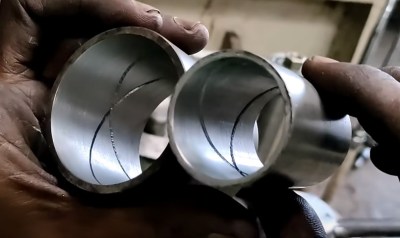
When you see something made from metal that seems like it would be impossible to manufacture, chances are good it was made with some variety of electrical discharge machining. EDM is the method of choice for hard-to-machine metals, high aspect ratio hole drilling, and precise surface finishes that let mating parts slip together with almost zero clearance. The trouble is, EDM is a bit fussy, and as a result hasn’t made many inroads to the home shop.

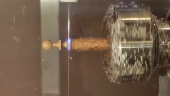
[Action BOX] aims to change that with a DIY wire EDM machine. In wire EDM, a fine brass wire is used as an electrode to slowly erode metal in a dielectric bath. The wire is consumable, and has to constantly move from a supply spool through the workpiece and onto a takeup spool. Most of the build shown in the video below is concerned with the wire-handling mechanism, which is prototyped from 3D-printed parts and a heck of a lot of rollers and bearings. Maintaining the proper tension on the wire is critical, so a servo-controlled brake is fitted to the drivetrain, which itself is powered by a closed-loop stepper. Tension is measured by a pair of strain gauges and Arduinos, which control the position of the shaft brake servo and the speed of the motor on the takeup spool.

Unfortunately, in testing this setup proved to live up to EDM’s fussy reputation. The brass wire kept breaking as soon as cutting started, and [Action BOX] never made any actual cuts. There’s certainly promise, though, and we’re looking forward to developments. For more on EDM theory, check out [Ben Krasnow]’s look at EDM hole-drilling.

Continue reading “Bringing The Power Of EDM To The Home Shop”

Wire ECM built from an Ender 3

Simple Mods Turn 3D Printer Into Electrochemical Metal Cutter

We’re not aware of any authoritative metrics on such things, but it’s safe to say that the Ender 3 is among the most hackable commercial 3D printers. There’s just something about the machine that lends itself to hacks, most of which are obviously aimed at making it better at 3D printing. Some, though, are aimed in a totally different direction.

As proof of that, check out this Ender 3 modified for electrochemical machining. ECM is a machining process that uses electrolysis to remove metal from a workpiece. It’s somewhat related to electric discharge machining, but isn’t anywhere near as energetic. [Cooper Zurad] has been exploring ECM with his Ender, which he lightly modified by replacing the extruder with a hypodermic needle electrode. The electrode is connected to a small pump that circulates electrolyte from a bath on the build platform, while a power supply connects to the needle and the workpiece. As the tool traces over the workpiece, material is electrolytically removed.

The video below is a refinement of the basic ECM process, which [Cooper] dubs “wire ECM.” The tool is modified so that electrolyte flows down the outside of the needle, which allows it to enter the workpiece from the edge. Initial results are encouraging; the machine was able to cut through 6 mm thick stainless steel neatly and quickly. There does appear to be a bit of “flare” to the cut near the bottom of thicker stock, which we’d imagine might be mitigated with a faster electrolyte flow rate.

If you want to build your own Ender ECM, [Cooper] has graciously made the plans available for download, which is great since we’d love to see wire ECM take off. We’ve covered ECM before, but more for simpler etching jobs. Being able to silently and cleanly cut steel on the desktop would be a game-changer.

Continue reading “Simple Mods Turn 3D Printer Into Electrochemical Metal Cutter”

Mini-lathe carriage wheel

Improving A Mini-Lathe With A Few Clever Hacks

Like many budget machinists, the delightfully optimistically named [We Can Do That Better] had trouble with some of the finer controls on his import mini-lathe. But rather than suffer through it, he chose to rectify the machine’s shortcomings and in the process, teach everyone a bunch of great tips.

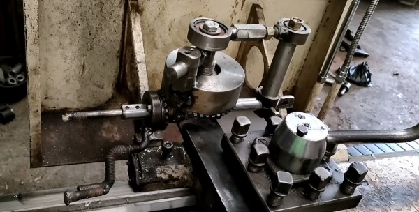
[We Can Do That Better]’s lathe retrofit focused on the carriage handwheel, which appears to lack proper bearings and wobbles around in a most imprecise manner. On top of that, the gearing of the drive made for an unsatisfying 19 mm of carriage travel per revolution of the handwheel. A single gear change made that an even 20 mm per rev, which when coupled with a calibrated and indexed handwheel ring greatly simplifies carriage travel measurements.

While the end result of the build is pretty great in its own right, for our money the best part of the video is its rich collection of machinist’s tips. The use of a wooden dowel and a printed paper template to stand in for a proper dividing head was brilliant, as was using the tailstock of the lathe to drive an engraving tool to cut the index lines. We’ve seen the use of a Dremel tool mounted to the toolpost to stand in for a milling machine before, but it’s always nice to see that trick used. And the mechanism for locking the dial to the handwheel was really clever, too.

Considering a mini-lathe? As encouraging as [We Can Do That Better]’s experience may be, it might be wise to take a deep dive into the pros and cons of such a machine.

Continue reading “Improving A Mini-Lathe With A Few Clever Hacks”

big LED flashlight

Own The Night With This Ludicrously Bright DIY Flashlight

If you’re a flashlight person, you know that there’s little you would do to get the brightest, most powerful, most ridiculous flashlight possible. You might even decide to build yourself a ludicrously powerful flashlight, like [Maciej Nowak] did.

If you choose the DIY route, be warned that it’s probably not going to be a simple process, at least if you follow [Maciej]’s lead. His flashlight is machined out of aluminum rounds, all turned down on the lathe to form the head of the flashlight. The head is made from three parts, each of which acts as a heat sink for the five 20-Watt CREE XHP70 LED modules. The LEDs are mounted with care to thermal considerations, and wired in series to DC-DC converter that provides the necessary 30 V using a battery pack made from four 21700 Li-ion cells. The electronics, which also includes a BMS for charging the battery and a MOSFET switching module, form a tidy package that fits into the aluminum handle.

The video below shows that the flashlight is remarkably bright, with a nice, even field with no hotspots. Given the 45-minute useful life and the three-hour recharge time, it might have been nice to make it so anywhere from one to five of the LEDs could be turned on at once. Some interesting effects might be had from switching the LEDs on sequentially, too.

Given the proclivities of our community, it’s no surprise that this is hardly the first powerful flashlight we’ve seen. This one broke the 100-Watt barrier with a single COB LED, while this ammo-can version sports an even higher light output. Neither of them looks much like a traditional flashlight, though, which is where [Maciej]’s build has the edge.

Continue reading “Own The Night With This Ludicrously Bright DIY Flashlight”

Big homemade lathe

Heavy Metal Lathe Build Doesn’t Spare The Steel

It’s common wisdom that the lathe is the essential machine tool, and the only one that can make copies of itself. While we won’t argue the primacy of the lathe in the machine shop, this scratch-built, heavy-duty lathe gives the lie to the latter argument — almost.

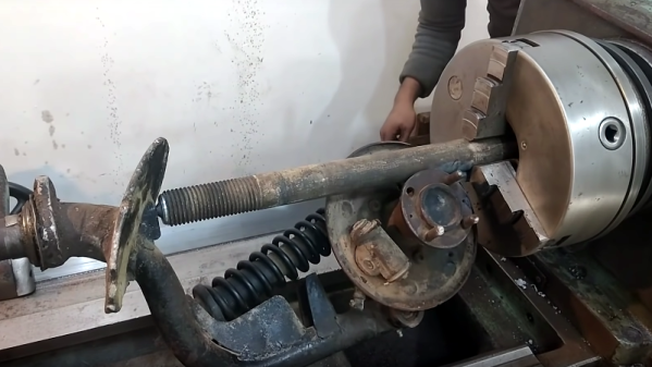
We’re used to seeing homebrew lathes, of course, and we’ve featured more than a few of them before. But two things make [Jornt]’s build stand out: how few specialized tools were needed to build it, and the sheer size and bulk of the finished product. Where most homebrew lathes tend to be the bench top variety and feature cast aluminum parts, [Jornt] went with steel for his build, and a lot of it. The base and bed of the machine are welded from scrap steel I-beams, and the ways are made from angle iron that has been ground flat with a clever jig to hold an angle grinder. The angle grinder plays a prominent role in the build, as do simple tools like a hand drill, files, and a welder — and yes, the unfinished lathe itself, which was used to bore out the bearing blocks for the headstock.

The completed lathe, powered by a treadmill motor in a way that [Jeremy Fielding] would no doubt endorse, comes in at a beefy 450 kg. It honestly looks like something you could buy from a catalog, and has most of the features of commercial machines. One thing we’d love to see on this lathe is the electronic lead screw that [James Clough] developed for his off-the-shelf lathe.

Continue reading “Heavy Metal Lathe Build Doesn’t Spare The Steel”

Klein Hidden Bolt and Tool

Tricky Screw Heads Have Disappearing Slots

Perhaps you’ve seen them, demonstrations of a machined piece of metal that upon further inspection is actually two pieces machined so perfectly that they appear as one. With extremely tight tolerances, it’s not possible to determine where one piece of metal ends and another begins — that is, until the secret is revealed. Inspired by such pieces of art, [Andrew Klein] sought to put this high level of machine work to practical use. And so it was that his as-yet-unnamed Screw With No Slot came to be.

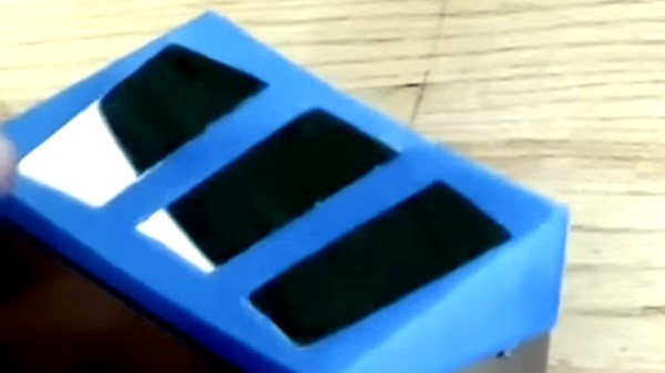
Klein Hidden Bolt depressed by brass rod
A brass rod pushes down to reveal the keyed center section.

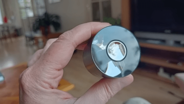
The screw’s disc-like appearance looks as if it’s a metal trim piece to cover a bolt hole. But in the video below [Andrew] shows us the trick, pushing a brass rod into the middle of the disc to reveal the hidden three-point slot. The center of the disk is actually a separate bit of finely machined metal that is spring loaded to stay flush. A specially designed wrench keys into the rounded concave triangle shape cut into the face.

The wrench is made with brass to avoid marring the precision surface. It uses three magnets to hold tight to the screw’s 410 magnetic stainless steel. [Andrew] didn’t spill the beans on how this was done, but we haven’t seen any process other than electrical discharge machining (EDM) that can achieve this level of mating precision. If that topic is new to you, we recommend checking out [Ben Krasnow’s] lab experiments on the topic.

We can’t help but be taken in by the beauty of the fastener, and it immediately sent our imaginations into a National Treasure induced dream-like state. [Andrew Klein] has yet to name this fastener, and he’s soliciting ideas for names in the video below the break. If you have such an idea, you can comment on his video. He’s also exploring the viability of the as-yet-named fastener as a commercial product for high end furniture builders.

This is not the first time we’ve featured [Andrew Klein]’s work. His previous featured projects include a custom sawblade for perfectly foldable joints and an unveiling of the magnetic magic behind switchable permanent magnets. Be sure to submit the neat hacks, builds, and inspiring projects that you come across to our Tip Line!

Continue reading “Tricky Screw Heads Have Disappearing Slots”

caliper jaw tools

Printable Caliper Jaws Increase Precision, Deflect Derision

If you’ve watched as many machining videos as we have, no doubt you’ve seen someone commit the cardinal sin of metalworking: using caliper jaws to scratch a mark into metal. Even if it’s a cheap Harbor Freight caliper rather than an expensive Starrett or Mitutoyo tool being abused, derision and scorn predictably rain down upon the hapless sinner’s head.

The criticism is not without its merit, of course. Recognizing this, [Nelson Stoldt] came up with these clamp-on nosepieces designed to turn calipers into a better marking tool. Using stock calipers as marking gauges always introduces some error, since the jaws are equal lengths and thus have to be held at a slight angle to the workpiece in order to make a mark. The caliper jaws correct for this admittedly negligible error by extending one jaw, allowing it to ride on a reference face while the other jaw remains perpendicular to the workpiece. As a bonus, the short jaw has a slot to mount a steel marking knife, saving the caliper jaws from damage.

[Nelson] chose to 3D-print his caliper jaws, but they could just as easily be milled from solid stock to make them a little more durable. Then again, you could always 3D-print the calipers in the first place, and integrate these jaws right into them.