The Padauk PMS150C is a terrible microcontroller. There are only six pins, there’s only one kiloword of Flash, 64 bytes of RAM, and it doesn’t do multiplication. You can only write code to this chip once, and the IDE uses 8-bit ints. [Anders] got his hands on some of these chips and decided to do something useful with them. It turns out that you can do a lot with minimal hardware, such as driving 300 RGB LEDs with a three cent microcontroller.
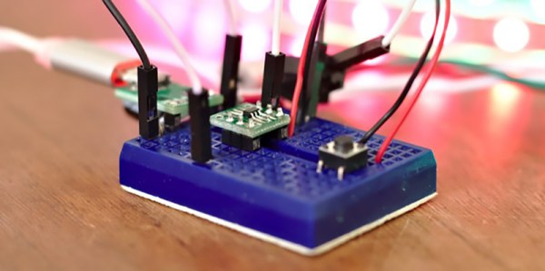
There’s some work trying to make an Open Source toolchain for these chips, but [Anders] decided to just go with the manufacturer IDE and programmer. What to do with a three cent microcontroller, though? Obviously something blinky. [Anders] connected this microcontroller to a strip of Neopixels, or WS2812Bs, but instead of driving them by giving each pixel a few bytes of RAM, the entire strip is being bitbanged one bit at a time. It’s some clever code, and even if [Anders] won’t be able to send images to a gigantic graphic display made of Neopixels, it’s still a neat trick.
At three cents and nearly zero associated hardware, this is the cheapest microcontroller we’ve ever seen. Even the minimalist PIC and AVR parts are on the orders of dozens of cents per part, and they still only have the functionality of this three-cent part. The manufacturer’s page has more details on the microcontroller itself including the data sheet, and you can check out the sizzle reel of this project below.
Continue reading “Making A Three Cent Microcontroller Useful”