Why 56k Modems Relied On Digital Phone Lines You Didn’t Know We Had

If you came of age in the 1990s, you’ll remember the unmistakable auditory handshake of an analog modem negotiating its connection via the plain old telephone system. That cacophony of screeches and hisses was the result of careful engineering. They allowed digital data to travel down phone lines that were only ever built to carry audio—and pretty crummy audio, at that.

Speeds crept up over the years, eventually reaching 33.6 kbps—thought to be the practical limit for audio modems running over the telephone network. Yet, hindsight tells us that 56k modems eventually became the norm! It was all thanks to some lateral thinking which made the most of the what the 1990s phone network had to offer.

Continue reading “Why 56k Modems Relied On Digital Phone Lines You Didn’t Know We Had”

All-Band Receiver Lets You Listen To All The Radio At Once

There are many ways to build a radio receiver, but most have a few things in common, such as oscillators, tuned circuits, detectors, mixers, and amplifiers. Put those together in the right order and you’ve got a receiver ready to tune in whatever you want to listen to. But if you don’t really care about tuning and want to hear everything all at once, that greatly simplifies the job and leaves you with something like this homebrew all-band receiver.

Granted, dispensing with everything but a detector and an audio amplifier will seriously limit any receiver’s capabilities. But that wasn’t really a design concern for [Ido Roseman], who was in search of a simple and unobtrusive way to monitor air traffic control conversations while flying. True, there are commercially available radios that tune the aviation bands, and there are plenty of software-defined radio (SDR) options, but air travel authorities and fellow travelers alike may take a dim view of an antenna sticking out of a pocket.

So [Ido] did a little digging and found a dead-simple circuit that can receive signals from the medium-wave bands up into the VHF range without regard for modulation. The basic circuit is a Schottky diode detector between an antenna and a high-gain audio amplifier driving high-impedance headphones; [Ido] built a variation that also has an LM386 amplifier stage to allow the use of regular earbuds, which along with a simple 3D-printed case aids in the receiver’s stealth.

With only a short piece of wire as an antenna, reception is limited to nearby powerful transmitters, but that makes it suitable for getting at least the pilot side of ATC conversations. It works surprisingly well — [Ido] included a few clips that are perfectly understandable, even if the receiver also captured things like cell phones chirping and what sounds like random sferics. It seems like a fun circuit to play with, although with our luck we’d probably not try to take it on a plane.

RFID From First Principles And Saving A Cat

[Dale Cook] has cats, and as he readily admits, cats are jerks. We’d use stronger language than that, but either way it became a significant impediment to making progress with an RFID-based sensor to allow his cats access to their litterbox. Luckily, though, he was able to salvage the project enough to give a great talk on RFID from first principles and learn about a potentially tragic mistake.

If you don’t have 20 minutes to spare for the video below, the quick summary is that [Dale]’s cats are each chipped with an RFID tag using the FDX-B protocol. He figured he’d be able to build a scanner to open the door to their playpen litterbox, but alas, the read range on the chip and the aforementioned attitude problems foiled that plan. He kept plugging away, though, to better understand RFID and the electronics that make it work.

To that end, [Dale] rolled his own RFID reader pretty much from scratch. He used an Arduino to generate the 134.2-kHz clock signal for the FDX-B chips and to parse the returned data. In between, he built a push-pull driver for the antenna coil and an envelope detector to pull the modulated data off the carrier. He also added a low-pass filter and a comparator to clean up the signal into a nice square wave, which was fed into the Arduino to parse the Differential Manchester-encoded data.

Although he was able to read his cats’ chips with this setup, [Dale] admits it was a long road compared to just buying a Flipper Zero or visiting the vet. But it provided him a look under the covers of RFID, which is worth a lot all by itself. But more importantly, he also discovered that one cat had a chip that returned a code different than what was recorded in the national database. That could have resulted in heartache, and avoiding that is certainly worth the effort too.

Continue reading “RFID From First Principles And Saving A Cat”

How Much Bandwidth Does CW Really Occupy?

Amateur radio license exams typically have a question about the bandwidths taken up by various modulation types. The concept behind the question is pretty obvious — as guardians of the spectrum, operators really should know how much space each emission type occupies. As a result, the budding ham is left knowing that continuous wave (CW) signals take up a mere 150 Hertz of precious bandwidth.

But is that really the case? And what does the bandwidth of a CW signal even mean, anyway? To understand that, we turn to [Alan (W2AEW)] and his in-depth look at CW bandwidth. But first, one needs to see that CW signals are a bit special. To send Morse code, the transmitter is not generating a tone for the dits and dahs and modulating a carrier wave, rather, the “naked” carrier is just being turned on and off by the operator using the transmitter’s keyer. The audio tone you hear results from mixing the carrier wave with the output of a separate oscillator in the receiver to create a beat frequency in the audio range.

That seems to suggest that CW signals occupy zero bandwidth since no information is modulated onto the carrier. But as [Alan] explains, the action of keying the transmitter imposes a low-frequency square wave on the carrier, so the occupied bandwidth of the signal depends on how fast the operator is sending, as well as the RF rise and fall time. His demonstration starts with a signal generator modulating a 14 MHz RF signal with a simple square wave at a 50% duty cycle. By controlling the keying frequency, he mimics different code speeds from 15 to 40 words per minute, and his fancy scope measures the occupied bandwidth at each speed. He’s also able to change the rise and fall time of the square wave, which turns out to have a huge effect on bandwidth; the faster the rise-fall, the larger the bandwidth.

It’s a surprising result given the stock “150 Hertz” answer on the license exam; in fact, none of the scenarios [Allen] tested came close to that canonical figure. It’s another great example of the subtle but important details of radio that [Alan] specializes in explaining.

Continue reading “How Much Bandwidth Does CW Really Occupy?”

A Single-Resistor Radio Transmitter, Thanks To The Power Of Noise

One of the great things about the Hackaday community is how quickly you find out what you don’t know. That’s not a bad thing, of course; after all, everyone is here to get smarter, right? So let’s work together to get our heads around this paper (PDF) by [Zerina Kapetanovic], [Miguel Morales], and [Joshua R. Smith] from the University of Washington, which purports to construct a low-throughput RF transmitter from little more than a resistor.

This witchcraft is made possible thanks to Johnson noise, also known as Johnson-Nyquist noise, which is the white noise generated by charge carriers in a conductor. In effect, the movement of electrons in a material thanks to thermal energy produces noise across the spectrum. Reducing interference from Johnson noise is why telescopes often have their sensors cooled to cryogenic temperatures. Rather than trying to eliminate Johnson noise, these experiments use it to build an RF transmitter, and with easily available and relatively cheap equipment. Continue reading “A Single-Resistor Radio Transmitter, Thanks To The Power Of Noise”

Impatience Is A Virtue When Testing This Old Maritime Teleprinter

[Larry Wall], inventor of Perl, once famously said that programmers have three key virtues: sloth, hubris, and impatience. It’s safe to say that these personality quirks are also present in some measure in most hardware hackers, too, with impatience being perhaps the prime driver of great hacks. Life’s too short to wait for someone else to build it, whatever it may be.

Impatience certainly came into play for [Sebastian (AI5GW)] while hacking a NAVTEX receiver (in German). The NAVTEX system allows ships at sea to receive text broadcast alerts for things like changes in the weather or hazards to navigation. The trouble is, each NAVTEX station only transmits once every four hours, making tests of the teleprinter impractical. So [Sebastian]’s solution was to essentially create his own NAVTEX transmitter.

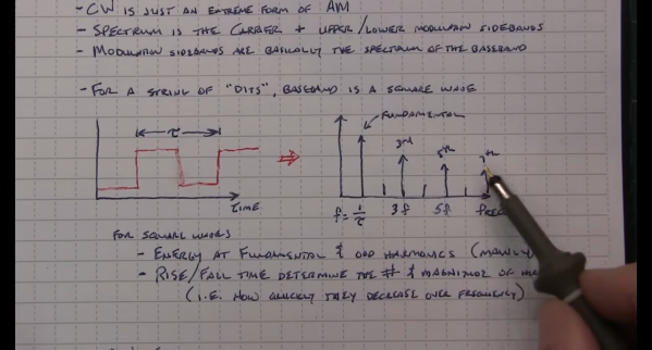
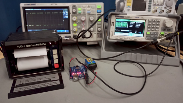
Job one was to understand the NAVTEX protocol, which is a 100-baud, FSK-modulated signal with characters encoded in CCIR 476. Since this encoding is also used in amateur radio teletype operations, [Sebastian] figured there would surely be an Arduino library for encoding and decoding it. Surprisingly, there wasn’t, but there is now, allowing an Arduino to produce the correct sequence of pulses for a CCIR 476-encoded message. Fed into a function generator, the mini-NAVTEX station’s signal was easily received and recorded by the painfully slow teleprinter. There’s that impatience again.

We thought this was a neat hack, and we especially appreciate that [Sebastian]’s efforts resulted in a library that could be useful to hams and other radio enthusiasts in the future. We’ve talked about some more modern amateur radio digital modes, like WSPR and FT8, but maybe it’s time to look at some other modes, too.

Continue reading “Impatience Is A Virtue When Testing This Old Maritime Teleprinter”

Abacus Synthesizer Really Adds Up

The abacus has been around since antiquity, and takes similar forms over the hundreds of cultures that have embraced it. It may be one of the first devices to be considered as having a “user interface” in the modern context — at least for simple arithmetic calculations. But using an abacus as the UI for a music synthesizer seems like something entirely new.

Part art concept project and part musical instrument, the “Abacusynth” by [Elias Jarzombek] is a way to bring a more visual and tactile experience to controlling a synth, as opposed to the usual knobs and switches. The control portion of the synth consists of four horizontal rods spanning two plywood uprights. Each rod corresponds to a voice of the polyphonic synth, and holds a lozenge-shaped spinner mounted on a low-friction bearing. Each spinner can be moved left and right on its rod, which controls the presence of that voice; spinning the slotted knob controls the modulation of the channel via photosensors in the uprights. Each rod has a knob on one side that activates an encoder to control each voice’s waveform and its harmonics.

In use, the synthesizer is a nice blend of electronic music and kinetic sculpture. The knobs seem to spin forever, so Abacusynth combines a little of the fidget spinner experience with the exploration of new sounds from the built-in speaker. The synth also has a MIDI interface, so it works and plays well with other instruments. The video below shows the hardware version of Abacusynth in action; there’s also a web-based emulation to try before you build.

Continue reading “Abacus Synthesizer Really Adds Up”