At this point, you’ve almost certainly heard of OctoPrint. The web-based control interface for 3D printers is especially popular for those who’s primary computers run on an operating system that has a penchant for occasionally imploding. Even if you aren’t laboring under that common software handicap, OctoPrint offers a wide away of compelling features. Perhaps chief among them the ability to monitor your printer over the network, and if you insist, over the Internet. But while OctoPrint provides the server side for getting your printer on the net, you’re on your own for the client.
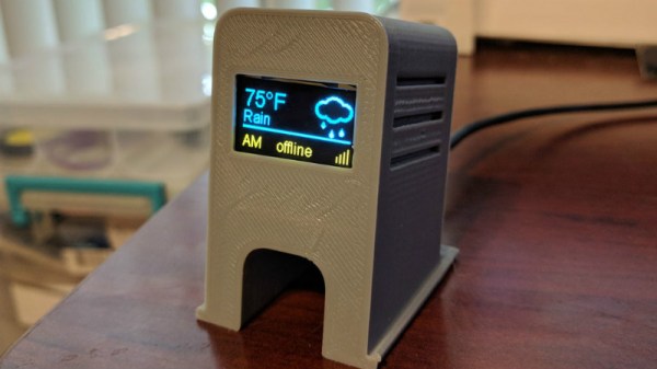
 Rather than using a web browser like some kind of peon, [David Payne] has come up with a very slick desktop OctoPrint monitor using the WeMos D1 Mini ESP8266 board. With an exceptionally low part count and housed in a (what else) 3D printed enclosure, this is a cheap and easy OctoPrint accessory that we suspect will be decorating many a hacker’s desk before too long.
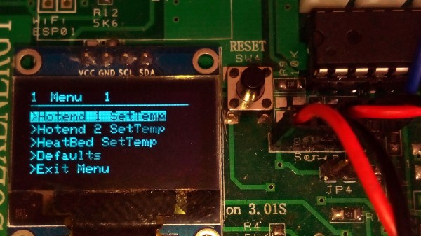
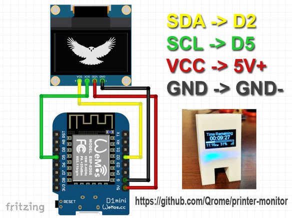
The electronics are simple to the extreme, just hook the 4 wires of an 128×64 OLED I2C display to the appropriate pins of the ESP8266 board, and you’re ready to upload the Arduino code [David] has come up with.
His code is very polished, from using WiFiManager for initial network setup to providing its own web-based configuration menus to get the device linked up to your OctoPrint instance, [David] clearly wanted this to be as smooth an experience as possible for the end user. When the 3D printer isn’t working on a job, the monitor will even switch over to showing you the time and weather. We’ve seen commercial products that weren’t this user-friendly.
We also love the case design on this little gadget. While the aesthetics are perhaps debatable (sort of reminds us of the little fellows from Darwinia), we appreciate any functional print that doesn’t require supports. You’ll need to provide a couple of little screws to keep the back panel on, but other than that everything snaps into place.
Of course, you could always just use your smartphone to keep an eye on OctoPrint, and even if the remote management capabilities don’t grab your interest, there’s plenty of interesting plugins to keep you occupied.
Continue reading “ESP8266 Monitor Keeps An Eye On OctoPrint”