First of all, we’d like to give a big shout-out to [Afrotechmods]! After a long hiatus, he has returned to YouTube with an awesome new video all about op-amp characteristics, looking at the relatively awful LM741 in particular. His particular way of explaining things has definitely helped many electronics newbies to learn new concepts quickly!
Operational amplifiers have been around for a long time. The uA741, now commonly known as the LM741, was indeed an incredible piece of technology when it was released. It was extremely popular through the 1970s and onward as it saved designers the chore of designing a discrete amplifier. Simply add a few external components, and you have a well-behaved amplifier.
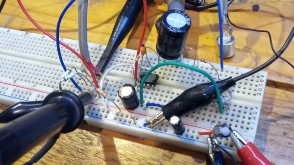
Before the invention of microelectromechanical system (MEMS) microphones, almost all microphones in cell phones and other electronics were a type of condenser microphone called the electret microphone. The fact that this type of microphone is cheap and easy enough to place into consumer electronics doesn’t mean they’re all low quality, though. Electret microphones can have a number of qualities that make them desirable for use recording speech or music, so if you have a struggling artist friend like [fvfilippetti] has who needs an inexpensive way to bring one to life, take a look at this electret microphone pre-amp.
The main goal of the project is to enhance the performance of these microphones specifically in high sound pressure level (SPL) scenarios. In these situations issues of saturation and distortion often occur. The preampl design incorporates feedback loops and an AD797 opamp to reduce distortion, increase gain, and maintain low noise levels. It also includes an output voltage limiter using diodes to protect against input overload and can adjust gain. The circuit’s topology is designed to minimize distortion, particularly in these high SPL situations.
Real-world testing of the preamp confirms its ability to handle high SPL and deliver low distortion, making it a cost-effective solution for improving the performance of electret microphones like these. If you want to go even deeper into the weeds of designing and building electret microphones and their supporting circuitry, take a look at this build which discusses some other design considerations for these types of devices.
A while back, [Chris Lu] was studying how analog circuits, specifically op-amps can be used to perform mathematical operations and wondered if they could be persuaded to solve differential equations, such as the wave equation. After sitting on the idea for a few years, it was time to make it a reality, and the result is an entry into the Op-Amp Challenge.
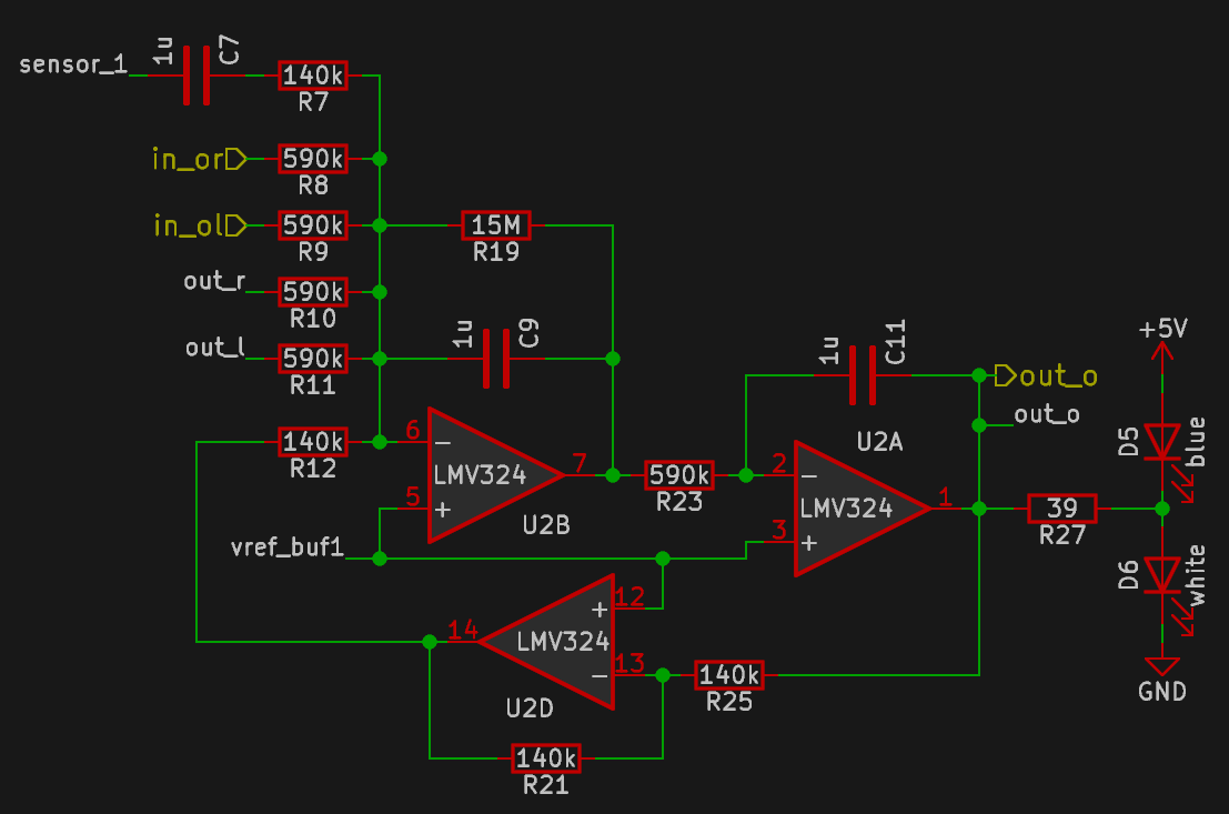
Unlike many similar interactive LED matrix displays that are digital in nature (because it’s a lot easier), this design is pure analog, using many, many op-amps. A custom PCB houses a 4×4 array of compute units, each with a blue and white LED indicating the sign and magnitude of the local signal.
The local input signal is provided by an IR photodiode, AC coupled to only respond to change, with every other circuit sharing a sensor to keep it simple. Each circuit is connected to its immediate neighbors on the PCB, and off the PCB via board-to-board connectors. This simple scheme makes this easily scalable if desired in the future.
[Chris] does a great job of breaking down the math involved, which makes this project a neat illustration of how op-amp circuits can implement complex mathematical problems in an easy-to-understand process. Even more op-amps are pressed into service for generating the split-rail voltage reference and for amplifying the weak photodiode signals, but the computation circuit is the star of the show.
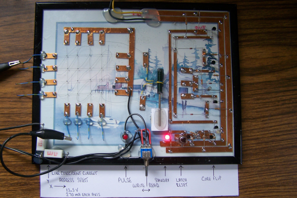
No matter how memory technology marches on, magnetic core memory is still cool. Radiation-hard, nonvolatile, and so pretty. What’s there not to love? [Mark Nesselhaus] is no stranger to fun in-your-face electronics builds — judging from his hackaday.io projects — and this entry to the Hackaday Op-Amp contest is no outlier. This is a sixteen-bit magnetic core RAM demonstrator built upon glass using copper tape and solder, which always looks great and is actually not all that hard to do yourself provided you grab a new scalpel blade from the pack before starting.
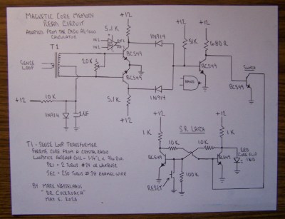
Transformer-coupled differential front-end amplifier driving an SR latch.
For the uninitiated, the crossed X and Y wires each host a hard magnetic toroid which can only be magnetised by a field beyond a certain threshold due to the shape of the B-H curve of ferrite materials. The idea is for a required threshold current, drive the selected X line and Y line each with a current half of this value, so that only the selected core bit ‘sees’ the full field value, and flips state. This means that only a single bit can be written for each core plane, so to form longer words these layers are stacked, producing some wonderful cubic structures. These magnetic circuits are responsible for putting a human on the moon.
Reading the bit state is basically the opposite. A third sense wire is passed sequentially through each bit in the array. By driving a current the opposite way through the selected core bit, if the core was previously magnetised then the sense wire will read a short pulse that can be amplified and registered. The eagle-eyed will realise that reading is a destructive process, so this needs to be followed up by a write-back process to refresh the bit, although the core state will persist without power, giving the memory nonvolatile behaviour.
[Mark] utilises a simple discrete transistor differential transformed-coupled front end which senses the tiny current pulse and passes it along to a Set-Reset latch for visualisation. This simple concept could easily be extended to make this a practical memory, but for now, addressing is courtesy of a pair of crocodile clips and a discrete write/read pulse switch. We will watch with interest how far this goes.
DIY core memory builds are not a regular occurrence around these parts, but we see them from time to time, like this polished 64-bit setup. Core arrays are not the only magnetic memory in town, we’ve also seen DIY core rope memories as well.
Circuit simulations are great because you can experiment with circuits and make changes with almost no effort. In Circuit VR, we look at circuits using a simulator to do experiments without having to heat up a soldering iron or turn on a bench supply. This time, we are going to take a bite of a big topic: op amps.
The op amp — short for operational amplifier — is a packaged differential amplifier. The ideal op amp — which we can’t get — has infinite gain and infinite input impedance. While we can’t get that in real life, modern devices are good enough that we can pretend like it is true most of the time.
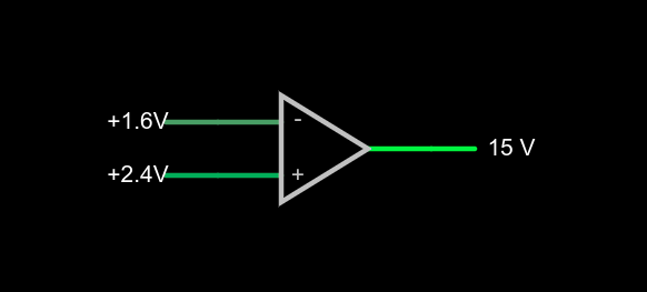
a very simple op amp circuit with some detail omitted
If you open this circuit in the Falstad simulator, you’ll see two sliders to the right where you can tweak the input voltage. If you make the voltages the same, the output will be zero volts. You might think that a difference amplifier would take inputs of 1.6V and 2.4V and either produce 0.8V or -0.8V, but that’s not true. Try it. Depending on which input you set to 2.4V, you’ll get either 15V or -15V on the output. That’s the infinite gain. Any positive or negative output voltage will quickly “hit the rail” or the supply voltage which, in this case, is +/-15V.
Practical Concerns
The biggest omitted detail in the schematic symbol above is that there’s no power supply here, but you can guess that it is +/- 15V. Op amps usually have two supplies, a positive and a negative and while they don’t have to be the same magnitude, they often are. Some op amps are specifically made to work with a single-ended supply so their negative supply can connect to ground. Of course, that presupposes that you don’t need a negative voltage output.
The amount of time it takes the output to switch is the slew rate and you’ll usually find this number on the device datasheet. Obviously, for high-speed applications, a fast slew rate is important, particularly if you want to use the circuit as a comparator as we are here.
Other practical problems arise because the op amp isn’t really perfect. A real op amp would not hit the 15V rail exactly. It will get close depending on how much current you draw from the output. The higher the current, the further away from the rails you get. Op amps will also have some offset that will prevent it from hitting zero when the inputs are equal, although on modern devices that can be very low. Some older devices or those used in high-precision designs will have a terminal to allow you to trim the zero point exactly using an external resistor.
Op Amps Can Provide Steady Voltage Under Variable Load
Rather than dig through a lot of math, you can deal with nearly all op amp circuits if you remember two simple rules:
The inputs of the op amp don’t connect to anything internally.
The output mysteriously will do what it can to make the inputs equal, as far as it is physically possible.
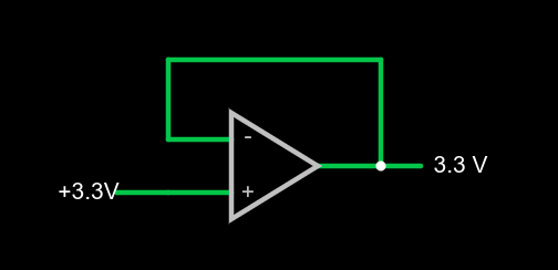
1x amplifier
That second rule will make more sense in a minute, but we already see it in action. Set the simulator so the – input (the inverting input) is at 0V and the noninverting input (+) is at 4V. The output should be 15V. The output is trying to make the inverting input match the noninverting one, but it can’t because there is no connection. The output would like to provide an infinite amount of voltage, but it can only go up to the rail which is 15V.
We can exploit this to make a pretty good x1 amplifier by simply shorting the output to the – terminal. Remember, our rules say the input terminals appear to not connect to anything, so it can’t hurt. Now the amplifier will output whatever voltage we put into it:
You might wonder why this would be interesting. Well, we will learn how to increase the gain, but you actually see this circuit often enough because the input impedance is very high (infinite in theory, but not practice). And the output impedance is very low which means you can draw more current without disturbing the output voltage much.
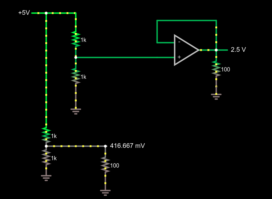
Comparing voltage divider performance with and without a 1x amplifier
This circuit demonstrates the power of a 1x amplifier. Both voltage dividers produce 2.5V with no load. However, with a 100 ohm load at the output, the voltage divider can only provide around 400mV. You’d have to account for the loading in the voltage divider design and if the load was variable, it wouldn’t be possible to pick a single resistor that worked in all cases. However, the top divider feeds the high impedance input of the op amp which then provides a “stiff” 2.5V to whatever load you provide. As an example, try changing the load resistors from 100 ohms to different values. The bottom load voltage will swing wildly, but the top one will stay at 2.5V.
Don’t forget there are practical limits that won’t hold up in real life. For example, you could set the load resistance to 0.1 ohms. The simulator will dutifully show the op amp sourcing 25A of current through the load. Your garden-variety op amp won’t be able to do that, nor are you likely to have the power supply to support it if it did.
What’s Being Amplified?
This is an amplifier even though the voltage stayed the same. You are amplifying current and, thus, power. Disconnect the bottom voltage divider (just delete the long wire) and you’ll see that the 5V supply is providing 12.5 mW of power. The output power is 62.5 mW and, of course, varies with the load resistor.
Notice how this circuit fits the second rule, though. When the input changes, the op amp makes its output equal because that’s what makes the + and – terminals stay at the same voltage.
Of course, we usually want a higher voltage when we amplify. We can do that by building a voltage divider in the feedback loop. If we put a 1:2 voltage divider in the loop, the output will have to double to match the input and, as long as that’s physically possible, that’s what it will do. Obviously, if you put in 12V it won’t be able to produce 24V on a 15V supply, so be reasonable.
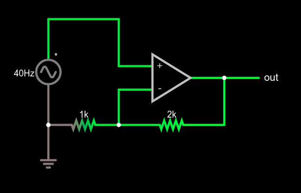
Non-inverting amplifier example
This type of configuration is called a non-inverting amplifier because, unlike an inverting amplifier, an increase in the input voltage causes an increase in the output voltage and a decrease in input causes the output to follow.
Note that the feedback voltage divider isn’t drawn like a divider, but that’s just moving symbols on paper. It is still a voltage divider just like in the earlier example. Can you figure the voltage gain of the stage? The voltage divider ratio is 1:3 and, sure enough, a 5V peak on input turns into a 15V peak on the output, so the gain is 3. Try changing the divider to different ratios.
What’s Next?
While it isn’t mathematically rigorous, thinking of the op amp as a machine that makes its inputs equal is surprisingly effective. It certainly made the analysis of these simple circuits, the comparator, the buffer amplifier, and a general non-inverting amplifier simple.
There are, of course, many other types of amplifiers, as well as other reasons to use op amps such as oscillators, filters, and other even more exotic circuits. We’ll talk about some of them next time and the idea of a virtual ground, which is another helpful analysis rule of thumb.
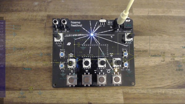
Cargo pants can fit drumsticks in the pockets if you don’t mind them sticking out. They can also hold this drum set and still have enough room for a pair of headphones, some pens, and a small notebook. At least, guy’s cargo pants can fit all that. Now your pocket is decked out with enough music gear to compose and drum few drum loops and even scribble some notes. We can’t speak for [Tomash Ghz] carrying a notebook, but he wanted a drum set in his pocket badly enough to make a custom circuit board to bring to the 2017 Fasma Festival in Athens. He wrote code for a Teensy 3.2 which fits on the back of his PCB next to a 9V battery. Don’t be afraid, the smallest components are 0805 so even clumsy fingers will be able to build their own. The Gerber files and BOM are all available, so nothing is stopping you.
On the board, we find an array of op-amps to support headphone and line-level outputs, four big ole’ buttons to activate each type of drum: kick, tom, snare, and hat. Then we have four potentiometers to change the sound of each like pitch, decay/length, modulation, and distortion. Once the perfect pattern is recorded, it can be saved in non-volatile memory in case you run out of juice although it can run up to seven-and-a-half hours on one battery. If you find yourself invested in the hardware, there is also a video walk-through about using the drum machine so grab your notebook and beat it.
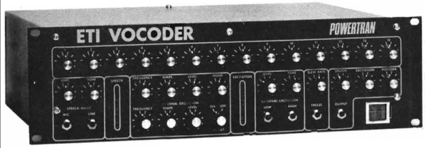
It is hard to remember that scant decades ago, electronic magazines — the pre-Internet equivalent of blogs — featured lots of audio circuits based on analog processing. Music synthesizers were popular for example, because microcontrollers were expensive and unable to perform digital signal processing tasks in the way you would use them today. [Julian] has been trying to build a vocoder from that era from ETI magazine. Along the way, he’s making videos documenting what he’s found and how’s he resolving issues.
The circuit generates levels for particular input frequencies. It does so with a two-op-amp bandpass filter, a two-op-amp rectifier, and then an op-amp lowpass filter. That’s five op-amps for each band (there are 14 bands) plus the support circuitry. And that’s just the input section! Today, you would simply sample the signal and do a fast Fourier transform (FFT) to get the same kind of data.