The term “adaptive optics” sounds like something that should be really complicated and really expensive. And in general, the ability to control the properties of optical elements is sufficiently difficult enough that it’s reserved for big-science stuff like billion-dollar space telescopes.
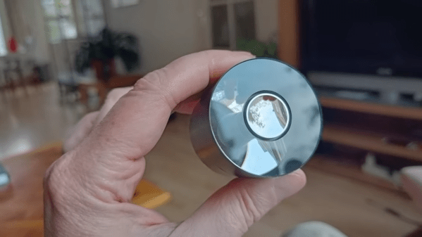
But that doesn’t mean there aren’t quick and dirty adaptive optics that are suitable for the budget-minded experimenter, like this thermally deformable mirror. As [Zachary Tong] explains, this project, which started quite some time ago, is dead simple — a 4 by 4 array of through-hole resistors stand on end, and these are attached to a glass coverslip that has been aluminized on one side. An Arduino and a couple of shift registers make it possible to individually address each of the 16 resistors in the array. Passing a current through a resistor heats it up a bit, leading to thermal expansion and a slight deflection of the mirror sitting on top of the array. Controlling which resistors heat up and by how much should lead to deformation of the mirror surface in a predictable way.
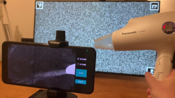
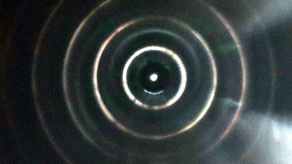
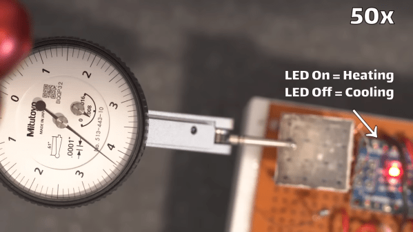
The video below shows some of [Zach]’s experiments with the setup. Unfortunately, he wasn’t able to fully demonstrate its potential — the low-quality mirror didn’t cooperate with his homebrew interferometer. He was, however, able to use a dial indicator to show deflection of the mirror in the 2- to 3-micron range by heating the array. That alone is pretty cool, especially given the dirt cheap nature of the build.
As for practical uses, don’t get too excited. As [Zach] points out, thermal systems like this will probably never be as fast as MEMS or piezoelectric actuators, and many use cases for adaptive optics really don’t react well to added heat. But changing the shape of a mirror with air pressure is another thing.
Continue reading “A Tiny Forest Of Resistors Makes For Quick And Dirty Adaptive Optics”