The Current Advances Of PCB Motors

There’s something to be said about the falling costs of printed circuit boards over the last decade. It’s opened up the world of PCB art, yes, but it’s also allowed for some experimentation with laying down fine copper wires inside a laminate of fiberglass and epoxy. We can design our own capacitive touch sensors. If you’re really clever, you can put coils inside four-layer PCBs. If you’re exceptionally clever, you can add a few magnets and build a brushless motor out of a PCB.

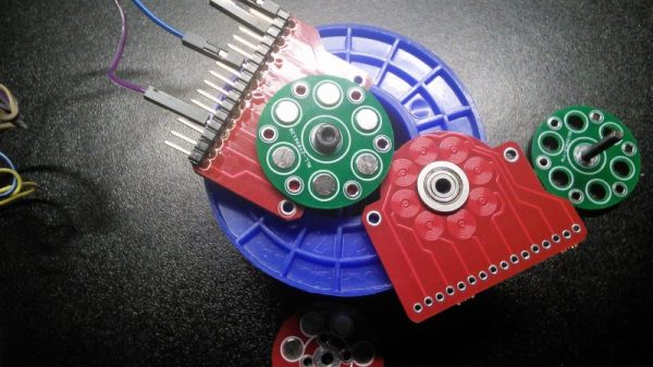
We first saw [Carl]’s PCB motor at the beginning of the year, but since then we’ve started the Hackaday Prize, [Carl] entered this project in the Prize, and this project already made it to the final round. It’s really that awesome. Since the last update, [Carl] has been working on improving the efficiency and cost of this tiny PCB motor. Part of this comes from new magnets. Instead of a quartet of round magnets, [Carl] found some magnets that divide the rotor into four equal pieces. This gives the rotor a more uniform magnetic field across its entire area, and hopefully more power.

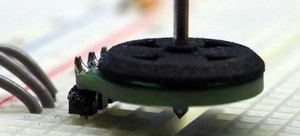
The first version of this 3D printed PCB motor used press-fit bushings and a metallic shaft. While this worked, an extra piece of metal will just drive up the cost of the completed motor. [Carl] has redesigned the shaft of the rotor to get rid of the metallic axle and replace it with a cleverly designed, 3D printed axle. That’s some very nice 3D printing going on here, and something that will make this motor very, very cheap.

Right now, [Carl] has a motor that can be made at any board house that can do four-layer PCBs, and he’s got a rotor that can be easily made with injection molding. The next step is closed-loop control of this motor. This is a challenge because the back-EMF generated by four layers of windings is a little weak. This could also be accomplished with a hall sensor, but for now, [Carl] has a working PCB motor. There’s really only one thing to do now — get the power output up so we can have real quadcopter badges without mucking around with tiny brushed motors.

[Carl] has put up a few videos describing how his PCB motor works; you can check those out below.
Continue reading “The Current Advances Of PCB Motors”

Stylish Business Card With A Stylophone Built In

If you’re in the electronics business, PCB business cards seem like a natural fit. They may be impractical and expensive, but they can really set you apart from that boring paper card from Vistaprint crowd. But they need to make sense for what you do, so for a musician and MIDI pro, this MIDI-controller stylophone business card is a real eye- and ear-catcher.

This business card is an idea that [Mitxela] has been kicking around for a while, and he even built a prototype a couple of years ago. The homebrew card, made using the spray paint, laser etching, and ferric chloride method, worked well enough as a proof of concept, but it was a little rough around the edges and needed the professional touch of a PCB fabricator. We’ve got to say that the finished cards are pretty darn sexy, with the black resist contrasting nicely against the gold-immersion pads. He selected a 1-mm thick board and made the USB connector as a separate small board; snapped off of the main board and reflowed back on, it builds up the edge connector to the proper thickness. The parts count is low — just an ATtiny85 and a resistor ladder to encode each key, with a simple jumper used as the stylus. The device itself is just a MIDI controller and makes no music on its own, but we still think this is a pretty creative way to hang out a shingle.

[Mitxela] has quite a few interesting builds, and is no stranger to our pages. Check out his recent servo-plucked MIDI music box, or these amazing miniature LED earrings.

Continue reading “Stylish Business Card With A Stylophone Built In”

Friday Hack Chat: Circuit Board Art

We are now in a golden age of printed circuit boards. It wasn’t too long ago that making your own circuit boards either involved a lot of money, or slightly less money and using some proprietary garbage PCB layout tool. Now, every board house speaks Gerber, and you can get a ten-pack of PCBs from China for five bucks. This incredible cost reduction means people are making art with printed circuit boards. We’ve seen portraits, landscapes, and memes. This is truly the beginning of a new artistic medium rendered in fiberglass and soldermask.

Check out this blinky bit of art nouveau. There is a facebook group for PCB paintings, and some of the Badgelife crew are relying on woodcut and linoleum engraving techniques to create works of art in copper and fiberglass.

For this week’s Hack Chat, we’re going to be talking all about PCB artwork. Our guest for this week’s Hack Chat will be [Andrew Sowa], an electrical engineer, a vocal advocate of KiCad, and the guy who made more of me money. The Benchoff Nickel was created by simply taking some of the fantastic illustrations from Hackaday’s own [Joe Kim] and applying KiCad’s Bitmap2Component tool. Since the creation of the nickel, [Andrew] has been working on extending his technique to cross-hatching, backlighting, and halftones.

In this Hack Chat, we’re going to be talking all about PCB artwork, including the very beginnings of PCB art where engineers hid a few easter eggs in the PCBs of Xboxen and other consumer electronics. Topics covered will be bitmap to SVG conversion (in Inkscape and Illustrator), KiCad footprint creation, and the more technical side of things with the limitations of PCB fabrication and the slightly different shades of beige FR4 comes in.

join-hack-chat

Our Hack Chats are live community events on the Hackaday.io Hack Chat group messaging. This week is just like any other, and we’ll be gathering ’round our video terminals at noon, Pacific, on Friday, April 20th. How can there be time zones when the Earth has four days simultaneously for each rotation? You erroneously measure time from one corner. Here’s a clock counting down the time until the Hack Chat starts.

Click that speech bubble to the right, and you’ll be taken directly to the Hack Chat group on Hackaday.io.

You don’t have to wait until Friday; join whenever you want and you can see what the community is talking about.

Magic 8 Ball Business Card Will Answer All Your Questions

The PCB business card has long been a staple amongst the freelance EE set. It’s a way to show potential clients that you can do the job, as well as leave a great first impression. Some are simple blinkenlights devices, others have contact information on USB storage. We reckon that [Seamus] has really hit it out of the park with this one, though.

That’s right- this business card riffs on the classic Magic 8-ball toy. Ask a question, shake the card, and it’ll light an LED with the corresponding answer to your query. Use it as a desk toy, or break deadlocks in meetings by looking to the card for the correct course of action.

It’s a very tasteful build, showing off [Seamus]’s minimalist chops – consisting of just a decade counter, a tilt sensor, and some LEDs. When the card is shaken, the tilt sensor outputs a series of pulses to the clock line of the decade counter, whose outputs are the 8 LEDs. When the tilt sensor settles, it lands on the final answer.

We think it’s a great card, which shows off both fundamental technical skills as well as a certain flair and creativity which can be key to landing exciting projects. It doesn’t hurt that it’s good fun, to boot. For another take on the Magic 8-ball, check out this build that can give you a Yes/No answer on demand.

A Brushless Motor On A PCB, Made From PCB

At Hackaday, we really appreciate it when new projects build on projects we’ve featured in the past. It’s great to be able to track back and see what inspires people to pick up someone else’s work and bring it to the next level or take it down a totally new path.

This PCB brushless motor is a great example of the soft collaboration that makes the Hackaday community so powerful. [bobricius] says he was inspired by this tiny PCB BLDC when he came up with his design. His write-up is still sparse at this point, but it looks like his motor is going to be used to drive a small robot. As with his inspiration, this motor has the stator coils etched right into the base PCB. But there are some significant improvements, like increasing the stator coil count from six to eight, as well as increasing the overall size of the motor. [bobricius] has also done away with the 3D-printed rotor of the original, opting to fabricate his rotor from stacked PCBs with cutouts for 5-mm neodymium magnets. We like the idea of using the same material throughout the motor, and it also raises the potential for stacking a second stator on the other side of the rotor, which might help mechanically and electrically. Even still, the prototype seems to hold its own in the video below.

This is [bobricius]’ second entry in the 2018 Hackaday Prize so far, after his not-a-Nixie tube display. Have you entered anything yet? Get to it! Prizes, achievements, and glory await.

Continue reading “A Brushless Motor On A PCB, Made From PCB”

Making Fancy Dice PCBs At Home

These days, it’s easy to get high-quality custom PCBs made and shipped to your door for under $50. It’s something that was unfathomable only a decade ago, but now it’s commonplace. However, it doesn’t mean that the techniques of home PCB production are now completely obsolete. Maybe you live somewhere a little off the beaten track (Australia, even!) and need to iterate quickly on a project, or perhaps you’d like to tinker with the chemical processes involved. For your learning pleasure, [Emiliano] decided to share some tips on making SMD-ready PCBs with the TinyDice project.

The actual project is to create a small electronic dice, and [Emiliano] touches on the various necessary considerations such as how to decrease power consumption, and how to source good quality, organic random numbers from your local microcontroller. Though its far from an exhaustive discussion on either topic, it shows an understanding of the deeper factors at play here.

However, the real meat of the write-up is the PCB production process. The guide goes through several stages of etching to not only prepare the PCB but also to add solder mask and produce a solder paste stencil as well using an aluminum can. This gives the boards that colored finish we’re all used to and lets the boards be reflowed for easy SMD assembly.

It’s a tidy guide as to how to approach producing your own boards to be used with SMD components, and it’s complete with clear photos and instructions throughout. If you want to take your designs up another notch, why not consider putting your components inside the circuit board?

Friday Hack Chat: Everything PCB

It was not too long ago that all PCB design packages were proprietary. Getting PCBs made was expensive, and if you tried to do this over the Internet, the best way was to download a board house’s proprietary software, design your board in their software suite, and send your boards off to be made. A 5 cm square board would cost two hundred dollars. I know this to be true because I’ve said it before, and no one has corrected me.

For this week’s Hack Chat, we’re talking Everything PCB with OSH Park. OSH Park is the leading creators of perfect purple PCBs. They have POGs, and for the last two weeks, they’ve been one of the few places you can send some Gerbers to and have it manufactured in a timely manner if you live in the US. Because China was closed.

For this week’s Hack Chat, we’re going to be talking about everything PCB. How do you do castellated holes? How do you mill slots and square or otherwise non-round holes? Internal cutouts? Stop mask expansion? Artwork? Panelization? Why purple? More POGs!

Our guests for this chat will be [Dan Sheadel] and [Drew Fustini] of OSH Park, and they’re going to be there answering all your questions. [Dan] has been around OSH Park from the beginning and enjoys designing tiny useless robots and mentoring students building better ones. [Drew] is an Open Source hardware developer, firmware designer, a BeagleBoard board member, and is usually found at hardware meetups wearing purple.

join-hack-chat

Our Hack Chats are live community events on the Hackaday.io Hack Chat group messaging. This Hack Chat is going down Friday, March 2nd at noon, Pacific time. Want to know what time this is happening in your neck of the woods? Have a countdown timer!

Click that speech bubble to the right, and you’ll be taken directly to the Hack Chat group on Hackaday.io.

You don’t have to wait until Friday; join whenever you want and you can see what the community is talking about.