Double Pendulum Uses Custom Slip Rings

Rotating mechanisms can be a headache when it becomes necessary to deliver power through them. [Igor Brkic] faced just such a challenge when creating his double-pendulum build, and solved it with a little DIY.

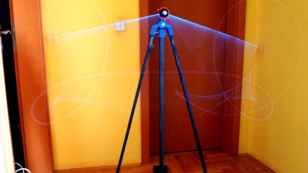
The project is known as KLAATNO, inspired by the Croatian word for pendulum, klatno. It’s a mechanical installation piece, consisting of a power-assisted pendulum, with a second pendulum fitted at the end of the swinging arm. A 24 volt geared motor is used to drive the assembly. It’s controlled by an Arduino Pro Mini, which measures the back EMF from the motor terminals to determine the speed and direction of the motor’s movement.

To make the installation more visually striking, EL wire was installed on the swinging arms of the twin pendulums. This required the transfer of power to the rotating assembly, which was achieved through the use of custom made slip rings. Copper sheet is used in combination with a flexible metal wire sourced from a guitar string. It’s not as low-friction as [Igor] would like, but it gets the job done.

It’s a fun installation that would be perfectly at home in the common area of any university engineering building. Of course, our favorite pendulums are of the siege weapon variety. Video after the break.

Continue reading “Double Pendulum Uses Custom Slip Rings”

Gesture Control Without Fancy Sensors, Just Pots And Weights

[Dennis] aims to make robotic control a more intuitive affair by ditching joysticks and buttons, and using wireless gesture controls in their place. What’s curious is that there isn’t an accelerometer or gyro anywhere to be seen in his Palm Power! project.

The gesture sensing consists not of a fancy IMU, but of two potentiometers (one for each axis) with offset weights attached to the shafts. When the hand tilts, the weights turn the shafts of the pots, and the resulting readings are turned into motion commands and sent over Bluetooth. The design certainly has a what-you-see-is-what-you-get aspect to it, and as a whole it works much like an inverted, weighted joystick hanging from one’s palm.

It’s an economical way to play with the idea of motion sensing, and when it comes to prototyping, being able to test a concept while keeping costs to a minimum is a good skill to have.

Clock This! A 3D-Printed Escapement Mechanism

Traditional mechanical clockmaking is an art that despite being almost the archetype of precision engineering skill, appears rarely in our world of hardware hackers. That’s because making a clock mechanism is hard, and it is for good reason that professional clockmakers serve a long apprenticeship to learn their craft.

Though crafting one by hand is no easy task, a clock escapement is a surprisingly simple mechanism. Simple enough in fact that one can be 3D-printed, and that is just what [Josh Zhou] has done with a model posted on Thingiverse.

The model is simply the escapement mechanism, so to make a full clock there would have to be added a geartrain and clock face drive mechanism. But given a pair of 608 skateboard wheel bearings and a suitable weight and string to provide a power source, its pendulum will happily swing and provide that all-important tick. We’ve posted his short video below the break, so if Nixie clocks aren’t enough for you then perhaps you’d like to take it as inspiration to go mechanical.

A pendulum escapement of this type is only one of many varieties that have been produced over the long history of clockmaking. Our colleague [Manuel Rodriguez-Achach] took a look at some of them back in 2016.

Continue reading “Clock This! A 3D-Printed Escapement Mechanism”

Inverted Pendulum For The Control Enthusiast

Once you step into the world of controls, you quickly realize that controlling even simple systems isn’t as easy as applying voltage to a servo. Before you start working on your own bipedal robot or scratch-built drone, though, you might want to get some practice with this intricate field of engineering. A classic problem in this area is the inverted pendulum, and [Philip] has created a great model of this which helps illustrate the basics of controls, with some AI mixed in.

Called the ZIPY, the project is a “Cart Pole” design that uses a movable cart on a trolley to balance a pendulum above. The pendulum is attached at one point to the cart. By moving the cart back and forth, the pendulum can be kept in a vertical position. The control uses the OpenAI Gym toolkit which is a way to easily use reinforcement learning algorithms in your own projects. With some Python, some 3D printed parts, and the toolkit, [Philip] was able to get his project to successfully balance the pendulum on the cart.

Of course, the OpenAI Gym toolkit is useful for many more projects where you might want some sort of machine learning to help out. If you want to play around with machine learning without having to build anything, though, you can also explore it in your browser.

Continue reading “Inverted Pendulum For The Control Enthusiast”

Electromagnet-Powered Pendulum

We’re always happy to see hackers inspired to try something different by what they see on Hackaday. To [SimpleTronic] has a project that will let you stretch your analog electronics skills in a really fun way. It’s an electromagnet pendulum analog circuit. Whether you’re building it, or just studying the schematics, this is a fun way to brush up on the non-digital side of the craft.

The pendulum is a neodymium magnet on the head of a bolt, dangling on a one foot aluminium chain. Below, a Hall Effect sensor rests atop an electromagnet — 1″ in diameter, with 6/8″ wire coiled around another bolt. As the pendulum’s magnet accelerates towards the electromagnet’s core, the Hall effect sensor registers an increase in voltage. The voltage peaks as the pendulum passes overhead, and as soon as the Hall Effect sensor detects the drop in voltage, the electromagnet flicks on for a moment to propel the pendulum away. This circuit has a very low power consumption, as the electromagnet is only on for about 20ms!

The other major components are a LM358N op-amp, a CD4001B quad CMOS NOR gate, and IRFD-120 MOSFET. [SimpleTronic] even took the time to highlight each part of the schematic in order to work through a complete explanation.

Continue reading “Electromagnet-Powered Pendulum”

Water Slide + Ferris Wheel = SlideWheel

This might be German engineering at its funnest. [Wiegand Maelzer GmbH] have created a new type of amusement park ride that combines the thrill of a water slide with the gentle revolutions of a Ferris wheel.

Inspired by the wish of a young Swiss boy in 2012, the whimsical feat of engineering known as the SlideWheel was realized this year. This is isn’t quite the giant sloshing drowning machine it appears to be on first blush, though. It begins and ends at the same shallow pool, where three- and four-person rafts are lifted into the ride by conveyor belt. What happens next is difficult to describe. It’s easier just to watch the first-person video below that demonstrates the pendulum-like motion that comes from floating while rotating.

SlideWheel moves at a modest 3 RPM, though this can be adjusted. Travel speed through the tube maxes out at 40 KPH/ 25 MPH, but will vary depending on the raft’s location, the position of the wheel, and gravity. The ride can handle up to three rafts at a time and delight 720 people per hour. A trip through the tube lasts a mere two minutes, but all those who’ve tried it say the experience seems much longer. [Wiegand Maelzer] have already received a few orders and are working on a dry version for malls and indoor amusement parks.

Not enough of an engineering feat, you say? Here’s a car-juggling robot.

Continue reading “Water Slide + Ferris Wheel = SlideWheel”

Harmonographs Generate Geometric Images Unique As Fingerprints

When my elder brother and I were kids back in the late 1970’s, our hacker Dad showed us this 1960-61 catalog of the Atlas Lighting Co (later Thorn Lighting) with an interesting graphic design on the cover. He told us to do a thought experiment, asking us to figure out how it would be possible to have a machine that would draw the design on that catalog cover.

Incorrectly, our first thought was that the design was created with a Spirograph. A spirograph has two main parts: a large ring with gear teeth on the inside and outside circumferences and a set of smaller, toothed wheels with holes in them for inserting a drawing instrument — usually a ball point pen. You hold the big ring, insert the pen in the smaller wheel, and then mesh and rotate the smaller wheel around the big ring. But spirographs can’t be used to draw irregular, asymmetrical figures. You could always recreate a design. Because of the nature of gears, none of them were unique, one off, designs.

A spirograph set like this cannot make the image above[Image credit: Multicherry CC-BY-SA 3.0]
A spirograph set like this cannot make the image above [Image credit: Multicherry CC-BY-SA 3.0]
We figured adding some lever arms, and additional geared wheels (compound gears) could achieve the desired result. It turns out that such a machine is called a Cycloid Drawing Machine. But even with this kind of machine, it was possible to replicate a design as often as required. You would fix the gears and levers and draw a design. If the settings are not disturbed, you can make another copy. Here’s a video of a motorized version of the cycloid machine.

The eventual answer for making such designs was to use a contraption called as the harmonograph. The harmonograph is unique in the sense that while you can make similar looking designs, it would be practically impossible to exactly replicate them — no two will be exactly the same. This thought experiment eventually led to my brother building his own harmonograph. This was way back when the only internet we had was the Library, which was all the way across town and not convenient to pop in on a whim and fancy. This limited our access to information about the device, but eventually, after a couple of months, the project was complete.

Continue reading “Harmonographs Generate Geometric Images Unique As Fingerprints”