These days we are blessed with multicore 64-bit monster CPUs that can calculate an entire moon mission’s worth of instructions in the blink of an eye. Once upon a time, though, the state of the art was much less capable; Intel’s first microprocessor, the 4004, was built on a humble 4-bit architecture with limited instructions. [Mark] decided calculating pi on this platform would be a good challenge.
It’s not the easiest thing to do; a 4-bit processor can’t easily store long numbers, and the 4004 doesn’t have any native floating point capability either. AND and XOR aren’t available, either, and there’s only 10,240 bits of RAM to play with. These limitations guided [Mark’s] choice of algorithm for calculating the only truly round number. Continue reading “Calculating Pi On The 4004 CPU, Intel’s First Microprocessor”→
It might take you some time to understand what’s happening in the video that Hackaday alum [Moritz Sivers] shared with us. This is [Moritz]’s contribution for this year’s Pi Day – a machine that shows digits of Pi in a (technically, not quite) infinite loop, and shows us a neat trick we wouldn’t have thought of.
The two main elements of this machine are a looped piece of thermochromic foil and a thermal printer. As digits are marked on the foil by the printer’s heating element, they’re visible for a few seconds until the foil disappears from the view, only to be eventually looped back and thermally embossed anew. The “Pi digits calculation” part is offloaded to Google’s pi.delivery service, a π-as-a-Service endpoint that will stream up to 50 trillion first digits of Pi in case you ever need them – an ESP8266 dutifully fetches the digits and sends them off to the thermal printer.
This machine could print the digits until something breaks or the trillions of digits available run out, and is an appropriate tribute to the infinite nature of Pi, a number we all have no choice but to fundamentally respect. A few days ago, we’ve shown a similar Pi Day tribute, albeit a more self-sufficient one – an Arduino calculating and printing digits of Pi on a character display! We could’ve been celebrating this day for millennia, if Archimedes could just count a little better.
Are you a math aficionado in need of a new desk toy? Then do we have the project for you. With nothing more than an Arduino and a seven-segment LED module, [Cristiano Monteiro] has put together a little gadget that will slowly work its way through the digits of Pi forever…or until you get bored of looking at it and decide to use the parts for something else.
On the hardware side, we really can’t overstate how simple this project is. A common four-digit LED display is connected up to an Arduino Nano, which is then plugged into the computer for power. [Cristiano] is using a breadboard here, but you could just as easily use four female-to-female jumpers to connect the two devices together. We suppose this would be a pretty good project for anyone who’s looking to get some practical experience with PCB design as well.
The real magic is in the software, which [Cristiano] has been kind enough to release under the MIT license. Calculating Pi on such a resource-constrained chip as the ATmega328P is far from ideal, but by porting over a C++ algorithm developed by [Xavier Gourdon] and [Pascal Sebah] for their paper Computation of the n-th Decimal Digit of π with Low Memory he was able to pull it off, albeit slowly.
The Musical Instrument Digital Interface has a great acronym that is both nice to say and cleanly descriptive. The standard for talking to musical instruments relies on a serial signal at 31250 bps, which makes it easy to transmit using any old microcontroller UART with a settable baud rate. However, [Kevin] has dived into explore the utility of sending MIDI signals over I2C instead.
With a bit of hacking at the Arduino MIDI library, [Kevin] was able to get the microcontroller outputting MIDI data over the I2C interface, and developed a useful generic I2C MIDI transport for the platform. His first tests involved using this technique in concert with Gravity dual UART modules. After he successfully got one running, [Kevin] realised that four could be hooked up to a single Arduino, giving it 8 serial UARTS, or, in another way of thinking, 8 MIDI outputs.
At its greatest level of development, [Kevin] shows off his I2C MIDI chops by getting a single Raspberry Pi Pico delivering MIDI signals to 8 Arduinos, all over I2C. All the Arduinos are daisy-chained with their 5V and I2C lines wired together, and the system basically swaps out traditional MIDI channels for I2C addresses instead.
There’s not a whole lot of obvious killer applications for this, but if you want to send MIDI data to a bunch of microcontrollers, you might find it easier daisy-chaining I2C rather than hopping around with a serial line in the classic MIDI-IN/MIDI-THRU fashion.
What happens when you mix over 23,000 coffee stirrers and a Raspberry Pi camera together? Probably nothing except for a mess, unless you very specifically pack the plastic straws and orient the camera just right. In that case, you get this very cool lenless digital straw camera that takes artfully ghostly images.
Image of Yoda photographed through many straws
Actually, lensless is a bit of a reach for [Adrian Hanft]’s creation. While the camera he’s using to grab the image has a lens, the objective, for lack of a better term, is just a tightly packed bundle of straws. We’ve seen this approach to photography before, but there the camera used film placed at the back of the straw bundles to capture the pixelated image.
Here, a ground glass screen stands in for the film; a long lightproof box behind that provide a place to mount a camera to capture the images. Cleverly, [Adrian] built the camera mount from Lego, allowing cameras and lenses to be quickly swapped out. A Nintendo gamepad controller talks to custom software running on a Raspberry Pi and allows the photographer to control exposure and scroll through pictures using a smartphone as a display. There’s a short build video below, for those who can’t get enough of straw-packing techniques.
As with the film version of this camera, we just love the look of the photographs that come from this — the texture of the straw honeycomb and the defocused subject make for a striking effect.
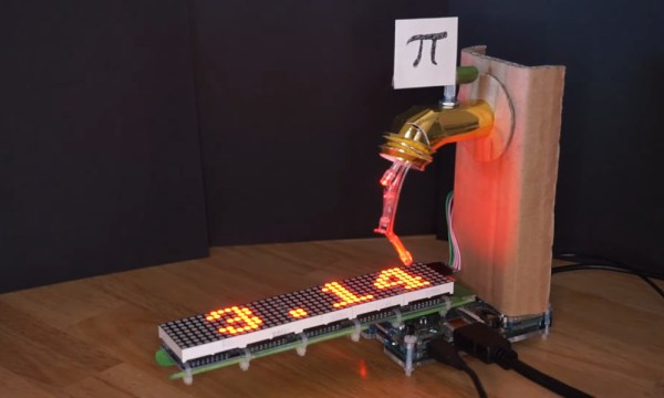
What did you do for Pi Day? Play with your Raspberry Pi 400? Eat some pizza or other typically round objects and recite all nine digits you’ve got memorized? That’s about where we were at this year. But not [bornach], no. [bornach] went all out and built a spigot that spews digits of Pi well past the first nine decimal places.
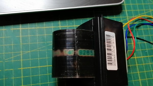
This clever spigot sculpture implements the spigot algorithm for generating digits of Pi one-by-one in a stream on to a chain of 8×8 matrices, and does so using a Raspberry Pi (of course). The point of the spigot algorithm is to store as few numbers as possible at any given time by reusing variables. We love the way the digits materialize on the matrix, almost as if they are ink being activated by water. Be sure to check out the build and demo video after the break.
That 10k pot on the top really does control the spigot — since the Pi has no ADC, [bornach] is using the potentiometer to charge a capacitor and using the time it takes to reach the threshold to decide whether the faucet is open or closed. There are a couple of hacks at play here, including the Popsicle-stick LED matrix bracing and the HAT [bornach] fashioned so the daisy-chained 8×8 LED modules could interface with the Pi.
It’ll be Pi Day when this article goes live, at least for approximately half the globe west of the prime meridian. We always enjoy Pi Day, not least for the excuse to enjoy pie and other disc-shaped foods. It’s also cool to ponder the mysteries of a transcendental number, which usually get a good treatment by the math YouTube community. This year was no disappointment in this regard, as we found two good pi-related videos, both by Matt Parker over at Standup Maths. The first one deals with raising pi to the pi to the pi to the pi and how that may or may not result in an integer that’s tens of trillions of digits long. The second and more entertaining video is a collaboration with Steve Mould which aims to estimate the value of pi by measuring the volume of a molecular monolayer of oleic acid floating on water. The process was really interesting and the results were surprisingly accurate; this might make a good exercise to do with kids to show them what pi is all about.
Remember basic physics and first being exposed to the formula for universal gravitation? We sure do, and we remember thinking that it should be possible to calculate the force between us and our classmates. It is, of course, but actually measuring the attractive force would be another thing entirely. But researchers have done just that, using objects substantially smaller than the average high school student: two 2-mm gold balls. The apparatus the Austrian researchers built used 90-milligram gold balls, one stationary and one on a suspended arm. The acceleration between the two moves the suspended ball, which pivots a mirror attached to the arm to deflect a laser beam. That they were able to tease a signal from the background noise of electrostatic, seismic, and hydrodynamic forces is quite a technical feat.
We noticed a lot of interest in the Antikythera mechanism this week, which was apparently caused by the announcement of the first-ever complete computational model of the ancient device’s inner workings. The team from University College London used all the available data gleaned from the 82 known fragments of the mechanism to produce a working model of the mechanism in software. This in turn was used to create some wonderful CGI animations of the mechanism at work — this video is well worth the half-hour it takes to watch. The UCL team says they’re now at work building a replica of the mechanism using modern techniques. One of the team says he has some doubts that ancient construction methods could have resulted in some of the finer pieces of the mechanism, like the concentric axles needed for some parts. We think our friend Clickspring might have something to say about that, as he seems to be doing pretty well building his replica using nothing but tools and methods that were available to the original maker. And by doing so, he managed to discern a previously unknown feature of the mechanism.
We got a tip recently that JOGL, or Just One Giant Lab, is offering microgrants for open-source science projects aimed at tackling the problems of COVID-19. The grants are for 4,000€ and require a minimal application and reporting process. The window for application is closing, though — March 21 is the deadline. If you’ve got an open-source COVID-19 project that could benefit from a cash infusion to bring to fruition, this might be your chance.
And finally, we stumbled across a video highlighting some of the darker aspects of amateur radio, particularly those who go through tremendous expense and effort just to be a pain in the ass. The story centers around the Mt. Diablo repeater, an amateur radio repeater located in California. Apparently someone took offense at the topics of conversation on the machine, and deployed what they called the “Annoy-o-Tron” to express their displeasure. The device consisted of a Baofeng transceiver, a cheap MP3 player loaded with obnoxious content, and a battery. Encased in epoxy resin and concrete inside a plastic ammo can, the jammer lugged the beast up a hill 20 miles (32 km) from the repeater, trained a simple Yagi antenna toward the site, and walked away. It lasted for three days and while the amateurs complained about the misuse of their repeater, they apparently didn’t do a thing about it. The jammer was retrieved six weeks after the fact and hasn’t been heard from since.