Whiteboard Clock

Whiteboard Clock Draws The Time

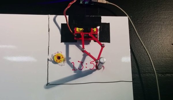
[Maurice] recently built a clock that draws the time (Google Doc) on a white board. We’ve seen plenty of clock hacks in the past, and even a very similar one. It’s always fun to see the different creative solutions people can come up with to solve the same problem.

This device runs on a PIC16F1454 microcontroller. The code for the project is available on GitHub. The micro is also connected to a 433MHz receiver. This allows a PC to keep track of the time, instead of having to include a real-time clock in the circuit. The USB connector is only used for power. All of the mounting pieces were designed in OpenSCAD and printed on a 3D printer. Two servos control the drawing arms. A third servo can raise and lower the marker to the whiteboard. This also has the added benefit of being able to place the marker tip inside of an eraser head. That way the same two servos can also erase the writing.

The communication protocol for this systems is interesting. The transmitter shows up on [Maurice’s] PC as a modem. All he needs to do to update the time is “echo 12:00 > /dev/whiteboard”. In this case, the command is run by a cron job every 5 minutes. This makes it easy to tweak the rate at which the time updates on the whiteboard. All communication is done one-way. The drawing circuit will verify the checksum each time it receives a message. If the check fails, the circuit simply waits for another message. The computer transmits the message multiple times, just in case there is a problem during transmission.

Plant Watering System

Automated Plant Watering System Uses Car Parts

[Shane] recently built an automated plant watering system for his home. We’ve seen several similar projects before, but none of them worked quite like this one. Shane’s system is not hooked into the house plumbing and it doesn’t use any off-the-shelf electronic valves.

Instead, [Shane’s] build revolves around a device that looks like it was intended to spray weed killer. The unit works sort of like a Super Soaker. The user fills the jug with water and then pumps a handle multiple times to build up some pressure inside the jug. Then a button can be pressed and the air pressure forces water out of the nozzle. [Shane] came up with a way to automate all of these mechanical motions.

First [Shane] had to find a way to pump up the bottle. He purchased a car door electronic lock actuator from eBay. It’s a pretty simple device. It’s just a DC motor with a gear box that turns the rotational motion of the motor into linear motion. This is mounted to a wooden jig and attached to the pump. A dsPIC microcontroller rotates the motor back and forth, which in turn pumps up the bottle.

The dsPic is also hooked up to a small servo. The servo is mounted to the same wooden jig as the car door actuator. A small arm is mounted to the servo so that when it rotates, the arm presses the pressure release button. This sends the water out of the bottles nozzle. [Pat] hooked up a small length of hose to the nozzle so he can direct the water into his plants. The video below demonstrates how the unit works. Continue reading “Automated Plant Watering System Uses Car Parts”

Watt Meter Build Walks You Through Power Measurement Basics

You almost never hear of a DC Watt Meter – one just does some mental math with Volts and Amps at the back of one’s head. An AC Watt Meter, on the other hand, can by pretty useful on any workbench. This handy DIY Digital AC Watt Meter not only has an impressive 30A current range, but is designed in a hand-held form factor, making it easy to carry around.

The design from Electro-Labs provides build instructions for the hardware, as well as the software for the PIC micro-controller at its heart. A detailed description walks you through the schematic’s various blocks, and there’s also some basics of AC power measurement thrown in for good measure. The schematic and board layout are done using SolaPCB – a Windows only free EDA tool which we haven’t heard about until now. A full BoM and the PIC code round off the build. On the hardware side, the unit uses MCP3202 12 bit ADC converters with SPI interface, making it easy to hook them up to the micro-controller. A simple resistive divider for voltage and an ACS-712  Hall Effect-Based Linear Current Sensor IC are the main sense elements. Phase calculations are done by the micro-controller. The importance of isolation is not overlooked, using opto-isolators to keep the digital section away from the analog. The board outline looks like it has been designed to fit some off-the-shelf hand-held plastic enclosure (if you can’t find one, whip one up from a 3D printer).

Although the design is for 230V~250V range, it can easily be modified for 110V use by changing a few parts. Swap the transformer, change the Resistive voltage divider values, maybe some DC level shifting, and you’re good to go. The one feature that would be a nice upgrade to this meter would be Energy measurements, besides just Power. For an inside look at how traditional energy meters work, head over to this video where [Ben Krasnow] explains KiloWatt Hour Meters


USB Cap

Never Forget Your USB Stick Again

USB sticks are very handy. They are a very portable and relatively inexpensive means of storing data. Possibly the most annoying part about using one of these devices is when you inevitable leave it behind somewhere by accident. This is especially true if it contains sensitive information. [Eurekaguy] feels your pain, and he’s developed a solution to the problem.

[Eurekaguy] designed a custom cap for USB sticks that beeps approximately every minute after the USB stick has been plugged in for five minutes. The cap is 3D printed and then slightly modified with four 1mm holes. Two wires are routed between these holes to make contact points for the VCC and GND pins of the USB stick.

The beep circuit is comprised of a tiny PIC12F629 microcontroller along with a couple of other supporting components. The circuit is wired together dead bug style to conserve space. Three AG5 batteries power the circuit. A small piezo speaker provides the repeating beep to remind you to grab your USB stick before you walk away from the computer.

[Thanks Irish]

Stereo Audio On A PIC32

The PIC microcontrollers are powerful little devices, and [Tahmid] is certainly pushing the envelope of what these integrated circuits can do. He has built (for educational purposes, he notes) an audio player based on a PIC32 and a microSD card. Oh, and this microcontroller-based audio player can play in stereo, too.

The core of the project is a PIC32MX250F128B microcontroller. 16-bit 44.1kHz WAV files are stored on the microSD card and playback is an impressive 12-bit stereo audio. It can also play back 8-bit files (with some difficulty). [Tahmid] programmed the interface to work through the serial port and it is very minimalistic, mostly because this was a project for him to explore audio on a microcontroller and wasn’t to build an actual stand-alone audio player that he would use from day to day.

Still, even though the project isn’t ready to replace your iPod, the core audio-processing parts are already done if you want to try to build on [Tahmid]’s extensive work. You could even build a standalone audio player like this but have it play high-quality 12-bit stereo audio!

Continue reading “Stereo Audio On A PIC32”

nixieclock

Simple And Elegant Single Digit Nixie Tube Clock

We’ve seen a few Nixie projects around here before, but this one might be the simplest yet. [Pinomelean] designed this simple nixie tube clock with just a handful of components.

The Nixie tube chosen for the project is an IN-12a. This tube can be purchased for around just four dollars. It is capable of displaying one digit at a time, zero through nine. Since the tube can only display one digit at a time, the clock is programmed to flash each digit of the current time one by one. There is a longer pause in between each cycle to make it easier to tell when the cycle begins and ends.

The system is broken into two main components. The first is the clock circuit. The clock runs off a PIC microcontroller with a 4MHz crystal. All of the logic is performed via the PIC and only a handful of other components are required. This includes some resistors and capacitors as well as a few high voltage SMD transistors to control the Nixie tube. [Pinomelean] has made this PCB design available so anyone can download it and make their own clock.

The second component to the clock is the power supply. The system is powered by a lithium-ion rechargeable battery, but [Pinomelean] notes that it can also be powered with USB. The lower voltage works well for the microcontroller, but the Nixie tube needs a higher voltage. [Pinomelean] built his own high voltage supply using components scavenged from an old disposable camera. This power supply board design is also made available for download, but it plugs into the main board so you can use another design if desired.. Check out the demo video below to see it in action. Continue reading “Simple And Elegant Single Digit Nixie Tube Clock”

Frappé Coffee Robot Offers Automated PIC-Me-Up

Although [Giorgos Lazaridis] has graced Hackaday several times, we’ve never covered the build of his frappé machine which reader [Jim] encountered after searching for information about the PIC16F1937. His site shows the build as in-progress, but he definitely has a working prototype here, and it’s definitely awesome.

Frappé coffee is made by mixing spray-dried instant coffee, a small amount of cold water, and sugar to taste in a manual shaker or a milkshake machine that uses a single beater. More water and/or milk is added as desired to top off the glass. The method was invented by accident in Thessaloniki, Greece, and has become quite popular.

In addition to sixteen pages of detailed build logs, [Giorgos] shot videos that demonstrate each of the modules that make up the machine. The operator puts a glass in a holder attached to a turntable. It moves first to the coffee and sugar dispenser, which fall through the same easily removable funnel. The next stop combines the add-water-and-beat steps beautifully. A length of hose strapped to the beater’s housing dispenses the initial cold water base. Then, the beater lowers automatically to beat the mixture. After mixing, the beater is drawn back up an inch or so, and more water is dispensed to rinse it off. Then the beater is fully withdrawn and the glass is filled the rest of the way. The final stop for the frappé is essential to the process: a bendy straw must be added. This is vitally important, and [Giorgos] handles it admirably with a stinger that shoots a straw into the glass.

[Giorgos]’s coffee robot is built around a PIC16F1937. He rolled his own PCB for the motherboard and each of the machine’s modules. There is a lot of logistical ingenuity going on in this project, and [Giorgos]’ build logs convey it all very well. Be sure to check out [Giorgos]’ machine in action after the break. The full set of eight videos that shows each module and culminates in the one below is well worth your time.

Continue reading “Frappé Coffee Robot Offers Automated PIC-Me-Up”