Op Amp Challenge: An Op-Amp Buck Regulator

Switching regulators have delivered such convenience and efficiency compared to their linear siblings, that it’s now becoming rare to see an old-style three-terminal regulator. Modern designs have integrated to such an extent that for many of us the inner workings remain something of a mystery. It’s still possible to make switching regulators from first principles though, which is what [Aaron Lager] has done by designing a buck regulator from a quad op-amp IC,

It’s an entry in our Op Amp Challenge and it appears to be a work in progress, but the design is solid enough. We’re no fans of the schematic style of representing an op-amp chip as a rectangle rather than individual op-amps, but it’s simply a PWM generator with a final op-amp used as a driver for the usual diode-inductor-capacitor network. We’re guessing that the op-amp driver won’t make this the most powerful of switchers, but in this case that’s hardly the point. Build this if you’re interested in taking an op-amp out of its normal sphere, or if you’re interested in the workings of a buck converter.

Need more in the way of switching regulators from first principles? We’ve got you covered, with the ultimate regulator kit of parts, the Fairchild UA723.

Spin Up To Speed With This Stroboscope

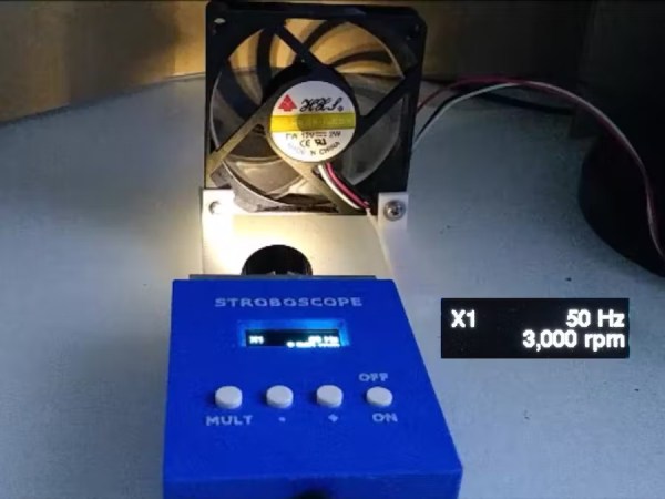
A stroboscope is not the most common tool, and while they can be purchased fairly inexpensively from various online stores, they are straightforward enough tools that plenty of us could build our own mostly from parts laying around. The basic idea is to shine a flashing light on a spinning object, and when it appears stationary the stroboscope will indicate the rotational speed. There are a few specialty parts that might not be in everyone’s parts drawers, though, and [John] shows us the ins-and-outs of his own DIY stroboscope.

The effect relies on extremely precise timing, and as such the most important part of a build like this is making sure to get the LED circuitry correct so its duty cycle and frequency can be tightly controlled. [John] is using a PT4115E driver board for the LED, and is using it to power a 1W white LED which also includes its own heat sink and lens. The controls for the stroboscope are handled by an ATtiny1614 microcontroller which shows its pulse rate on a small screen. The user can control the rate the LED flashes with simple controls, and when the spinning object appears to come to a stop the only thing left to do is read this value off of the screen.

While it might seem like an overly niche tool, stroboscopes have plenty of day-to-day uses. Older cars that used a central distributor made use of a specialty stroboscope called a timing light in order to properly advance the ignition timing of the engine. They also retain some use in medical applications, and plenty of older readers may be familiar with their use adjusting the speed on record players. They can also be used to make sure the shutter speeds on cameras are calibrated correctly.

Continue reading “Spin Up To Speed With This Stroboscope”

DIY Fume Extractor With ATtiny13 Speed Control

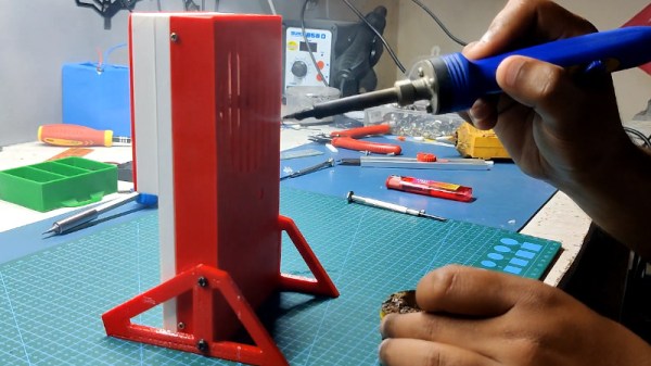
Let’s be honest, commercially-available soldering fume extractors are cheap enough that you probably don’t need to build one yourself. But it still makes for a good starter project, especially if you go out of your way to really flex your maker muscles like [Arnov Sharma] did with this tidy build.

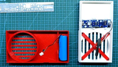
All the hallmarks of modern hardware making are on display here — you’ve got the 3D printed enclosure, a motor salvaged from a cheap toy quadcopter, and a custom PCB which uses the ATtiny13 and an AO4406 MOSFET to implement a PWM speed control.

The first press of the button starts the motor off at max speed, but keep pushing it, and the motor’s speed will ramp down until it turns off entirely. There’s even a TP4056 charge controller to top off the internal 18650 cell when the fume extractor is connected to a USB power source.

Is it over-engineered? Perhaps. But projects like these are a great opportunity to practice your skills, whether it’s PCB design or creating bespoke 3D printed enclosures. In the era of cheap 32-bit microcontrollers, it’s also refreshing to see hackers still dragging the ATtiny from time to time.

Continue reading “DIY Fume Extractor With ATtiny13 Speed Control”

Monochrome LCD Video Hacks Galore!

[Wenting Zhang] is clearly a fan of old school STN LCD displays, and was wondering how various older portable devices managed to drive monochrome LCDs panels with multiple grey levels. If the display controller supports multiple bits per pixel, it can use various techniques, such as PWM, in order to produce a pseudo-grayscale image. But, what if you have a monochrome-only display controller? With a sufficiently high pixel clock, can you use software on the application side of things to flip those pixels in such a manner as to give a reasonable looking grayscale image?

Simple dithering – don’t look too close!
PDM greyscale approximation in a 1-bit display

[Wenting] goes through multiple techniques, showing the resulting image quality in a clear, systematic manner. The first idea is to use a traditional dithering technique. For each pixel, it is set to black if the grey value is below some threshold. The resulting error value, is then propagated to neighbouring pixels. This error diffusion process smears the error out over the whole display, so spatially speaking, on average the pixel values correspond roughly to the original gray values. But, the pixels themselves are still either on or off. This isn’t quite enough. The next idea is to PWM the individual pixels over multiple frames, to approximate different grey levels. But, that gives a worst case effective refresh rate of 8 Hz with a PWM period of 15 frames, at 120 fps, and that flickers. Badly. One way to mitigate that is to switch to PDM (pulse density modulation) which selects different length sequences to give the same duty cycle but at higher frequency, at least for some grey values. Slightly better, but there’s more that can be done. Continue reading “Monochrome LCD Video Hacks Galore!”

Pitch Sequencer Turns Tascam Tape Deck Into Instrument

The cool thing about magnetic tape is that by varying the speed at which you play it back, you can vary the pitch of the output. [Issac] decided to take advantage of this, executing a fancy digitally-controlled pitch mod on his Tascam Porta 02 tape deck.

The build uses a Raspberry Pi Pico, which employs PWM to control the speed of the tape drive’s motor. This is achieved with the use of an NPN transistor driven by the PWM output of the Pico. This allows accurate control of motor speed, and thus pitch.

With that sorted out, the project was fleshed out with an OLED screen and a rotary encoder. These allow various patches or scripts to be run on the Pico, controlling the motor speed of the tape player in various ways. With a bit of work, [Issac] was also able to create a function that converted MIDI note values into PWM values that determine various motor speeds.

The natural thing to do next was to put in a tape with a looping sample at a set pitch, and then vary it in a sequence controlled by the Pico. The 8 steps of the sequence can be manually set with the rotary control, and in future, [Issac] even plans to add a real MIDI input, allowing the system to act as a monophonic synth.

If you prefer other routes to pitch shifting shenanigans, check out this project. Video after the break.

Continue reading “Pitch Sequencer Turns Tascam Tape Deck Into Instrument”

Mini MIDI Synth Uses Minimum Number Of Parts

The 80s were the golden age of synthesizers in pop music. Hugely complicated setups that spared no expense were the norm, with synths capable of recreating anything from pianos and guitars to percussion, strings, and brass. These types of setups aren’t strictly necessary if you’re looking to make music, though, especially in the modern age of accessible microcontrollers. This synthesizer from [Folkert] with MIDI capabilities, for example, creates catchy tunes with only a handful of parts.

This tiny synth is built around an ESP32 and works by generating PWM signals normally meant for LEDs. In this case, the PWM signals are sent through a rudimentary amplifier and then on to an audio output device.  That could be a small speaker, an audio jack to another amplifier, or a capture device.

The synth’s eight channels use up most of the ESP32’s I/O and provide a sound that’s reminiscent of the eight-bit video game era. The total parts count for this build is shockingly small with only a handful of resistors, the ESP, an optocoupler, and a few jacks.

For those wishing to experiment with synthesizers, a build like this is attractive because it’s likely that all the parts needed are already sitting around in a drawer somewhere with possibly the exception of the 5 pin DIN jacks needed for MIDI capabilities. Either way, [Folkert] has made all of the schematics available on the project page along with some sample mp3 files. For those looking to use parts from old video game systems sitting in their parts drawer, though, take a look at this synthesizer built out of a Sega Genesis.

Processing Audio With The RP2040

The Raspberry Pi, although first intended as an inexpensive single-board computer for use in education, is now ubiquitous in electronics communities. Its low price as well as Linux platform and accessible GPIO make it useful in many places outside the classroom. But, if you want to abandon the ease-of-use in favor of an even lower price, the Raspberry Pi foundation makes that possible as well with the RP2040 chip, commonly found on the Pico. [Jason] shows us one way to make use of this powerful chip by putting one in an audio digital signal processing board.

While development boards are available for this chip, [Jason] has opted instead for a custom PCB which he designed himself and includes an integrated headphone amplifier and 3.5 mm audio jacks. To do the actual DSP work, the RP2040 chip uses three 12-bit ADC channels and 16 controllable PWM channels. The platform is also equipped with the TLV320AIC3254 codec from Texas Instruments. With all of this put together, he has a functioning open-source platform he calls the DS-Pi.

[Jason] has built this as a platform for guitar effects and as a customizable guitar amp modeler, but with a platform that is Arduino-compatible and fairly easy to program it could be put to use for anything involving other types of music or audio processing, like this specialized MIDI-compatible guitar effects platform which is built around the same processor.