Retrotechtacular: The Omega Navigational System

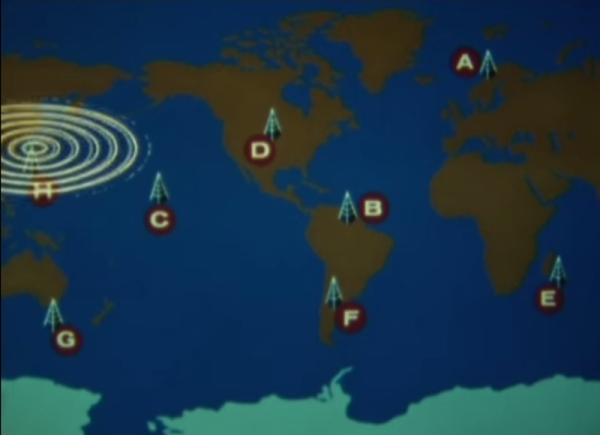
In 1971, the United States Navy launched the Omega navigational system for submarines and surface ships. The system used radio frequencies and phase difference calculations to determine global position. A network of eight (VLF) transmitter sites spread around the globe made up the system, which required the cooperation of six other nations.

Omega’s fix accuracy was somewhere between one and two nautical miles. Her eight transmitter stations were positioned around the Earth such that any single point on the planet could receive a usable signal from at least five stations. All of the transmitters were synchronized to a Cesium clock and emitted signals on a time-shared schedule.

LOP-thumb
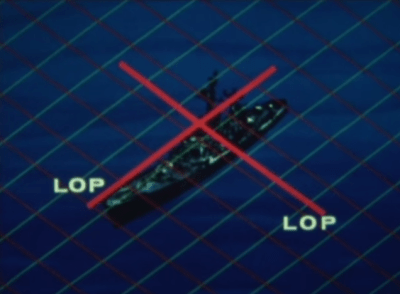
A ship’s receiving equipment performed navigation by comparing the phase difference between detected signals. This calculation was based around “lanes” that served to divvy up the distance between stations into equal divisions. A grid of these lanes formed by eight stations’ worth of overlapping signals provides intersecting lines of position (LOP) that give the sailor his fix.

In order for the lane numbers to have meaning, the sailor has to dial in his starting lane number in port based on the maps. He would then select the pair of stations nearest him, which were designated with the letters A to H. He would consult the skywave correction tables and make small adjustments for atmospheric conditions and other variances. Finally, he would set his lane number manually and set sail.

Continue reading “Retrotechtacular: The Omega Navigational System”

Beach Sign

LED Sign Brightens Up The Beach After Dark

[Warrior_Rocker’s] family bought a fancy new sign for their beach house. The sign has the word “BEACH” spelled vertically. It originally came with blue LEDs to light up each letter. The problem was that the LEDs had a narrow beam that would blind people on the other side of the room. Also, there was no way to change the color of the LEDs, which would increase the fun factor. That’s why [Warrior] decided to upgrade the sign with multi-colored LEDs.

After removing the cardboard backing of the sign, [Warrior] removed the original LEDs by gently tapping on a stick with a hammer. He decided to use WS2811 LED pixels to replace the original LEDs. These pixel modules support multiple colors and are individually addressable. This would allow for a wide variety of colors and animations. The pixels came covered in a weatherproof resin material. [Warrior] baked the resin with a heat gun until it became brittle. He was then able to remove it entirely using some pliers and a utility knife. Finally, the pixels were held in place with some hot glue.

Rather then build a remote control from scratch, [Warrior] found a compatible RF remote under ten dollars. The LED controller was removed from its housing and soldered to the string of LEDs. It was then hot glued to a piece of cardboard and placed into the sign’s original battery compartment. Check out the video below for a demonstration. Continue reading “LED Sign Brightens Up The Beach After Dark”

Building Your Own SDR-based Passive Radar On A Shoestring

Let’s start off with proof. Below is an animation of a measurement of airplanes and meteors I made using a radar system that I built with a few simple easily available pieces of hardware: two $8 RTL software defined radio dongles that I bought on eBay, and two log-periodic antennas. And get this, the radar system you’re going to build works by listening for existing transmissions that bounce off the targets being measured!

I wrote about this in a very brief blog posting a few years ago. It was mainly intended as a zany little side story for our radio telescope blog, but it ended up raising a lot of interest. Because this has been a topic that keeps attracting inquiries, I’m going to explain how I did the experiment in more detail.

It will take a few posts to show how to build a radar capable of performing these types of measurements. This first part is the overview. In later postings I will go through more detailed block diagrams of the different parts of a passive radar system, provide example data, and give some Python scripts that can be used to perform passive radar signal processing. I’ll also go through strategies to determine that everything is working as expected. All of this may sound like a lot of effort, but don’t worry, making a passive radar isn’t too complicated.

Let’s get started!

Continue reading “Building Your Own SDR-based Passive Radar On A Shoestring”

Retrotechtacular: The Spirit Of Radio

Many of us still tune in to terrestrial radio for one reason or another, be it baseball games, talk radio, or classic rock. But do you know how the sound is transmitted to your receiver? This week, our spotlight shines upon a short film produced by KYW Radio that serves as a cheerful introduction to the mysteries of amplitude modulation (AM) radio transmission as they were in 1940.

Sound vibrations enter a microphone and are converted to electrical current, or an audio waveform. The wave is amplified and sent several miles away to the transmitting station. During this trip, the signal loses power and so is amplified at the transmitting station in several stages. This audio wave can’t be transmitted by itself, though; it needs to catch a ride on a high-frequency carrier wave. This wave is generated on-site with a huge crystal oscillator, then subjected to its own series of amplifications prior to broadcast.

The final step is the amplitude modulation itself. Here, the changing amplitude of the original audio wave is used to modulate that of the high-frequency carrier wave. Now the signal is ready to be sent to the tower. Any receiver tuned in to the carrier frequency and in range of the signal will capture the carrier wave. Within the reciever, these currents are converted back to the vibrations that our ears know and love.

Continue reading “Retrotechtacular: The Spirit Of Radio”

Hackaday Prize Entry: Ground Penetrating Radar

This year’s Hackaday Prize is heating up, and right now there are quite a few projects in the works covering domains that are rarely, if ever, seen coming out of a garage or a workshop. One of the most interesting is [Glenn Powers]’ Open Ground Penetrating Radar. It’s exactly what the title says: an open-source radar system that can see into the Earth for less than $500.

While ground penetrating radar is great for archaeology and people searching for hoards buried in the middle of farmland, the biggest application is safety. You need only to Google “Florida sinkhole” to see the value of peering into the Earth.

[Glenn] is building his ground penetrating radar with a bare minimum of parts. A Baofeng VHF/UHF My First Radio™ serves as the signal generator, the controller is just an optoisolator, and the switch controller is a 7404 hex inverter. It literally can’t get simpler than that.

Of course these components can only be assembled into a simple radar, and the real value of a ground penetrating radar is the ability to map an area. For that, [Glenn] is bringing out a Pi and a GPS dongle to control the whole thing. Visualization is provided by none other than the US Navy. If it works for submarines, it should work for a metal cart, right?

It’s a great project, not only in the fact that it could help a whole bunch of people, but as a prime example of doing so much without tens of thousands of dollars in test equipment.


The 2015 Hackaday Prize is sponsored by:

Cyclist Pulled Over For Headphones Builds Neighborhood Shaking Bicycle Boombox

Riding around with headphones on is not the safest of things; those people are trying to could hit you! [Victor Frost] was actually pulled over for doing it. Although the bicycle police didn’t ticket him, they did push him over the edge to pursuing a compromise that lets him listen to tunes and perhaps still hear the traffic around him.

The build puts 200 Watts of audio on his rear luggage rack. He used a couple of file totes as enclosures, bolting them in place and cutting one hole in each to receive the pair of speakers. The system is powered by two 6V sealed lead-acid batteries which are topped off by a trickle-charger when the bike is parked.

Looking through this log we almost clicked right past this one. It wasn’t immediately apparent that this is actually version four of the build, and these are completely different spins each time. The top-down view of plastic-tacklebox-wrapped-v3 is sure to make you grin. Video overviews of the first two versions are linked in [Victor’s] details section of the project page linked at the top of this post. The progress is admirable and fun time digging through. They’re all quite a bit different but bigger, better, and more self-contained with each iteration.

Okay, okay, maybe this isn’t going to shake the neighborhood… until he adds a Bass Cannon to it.

Transmitting HD Video From A Raspberry Pi

It’s been a few years since the RTL-SDR TV Tuner dongle blew up the world of amateur radio; it’s a simple device that listens in on digital television frequencies, but it’s one of those tools that’s just capable enough to have a lot of fun. Now, we have a transmitting dongle. It’s only being used to transmit live HDTV from a Pi, but that in itself is very interesting and opens up a lot of possible builds.

The key piece of hardware for this build is a UT-100C DVB-T modulator. It’s a $169 USB dongle capable of transmitting between 1200-1350 MHz, and with a special edition of OpenCaster it’s possible to transmit over-the-air TV. There’s no amplifier, so you won’t be sending TV very far, but it does work.

On the Raspberry Pi side of the build, the standard camera captures H.264 video with raspivid, which is converted to a DVB compliant stream using ffmpeg. These are well-worn bits of software in the Raspberry Pi world, and OpenCaster takes care of the rest.

While this seems like the perfect solution to completely overbuilt quadcopters, keep in mind transmitting on the 23cm band does require a license. Transmitting in the UHF TV bands is a bad idea.