Lightsaber Uses Pogo Pins To Make Assembly A Breeze

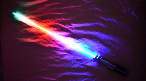
There was an endless supply of fantastic projects at Supercon this year, but one whose fit and finish really stood out was [Scott]’s lightsaber. If you were walking around and saw someone with a very bright RGB device with a chromed-out handle hanging off their belt it was probably this, though it may have been hard to look at directly. On the outside, the saber looks like a well-polished cosplay prop, and it is! But when Scott quickly broke down the device into component pieces it was apparent that extra care had been put into the assembly of the electronics.

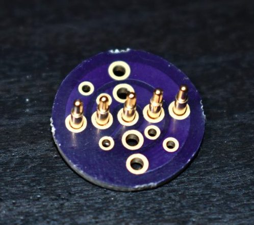
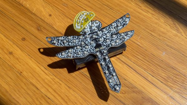
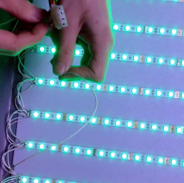
Like any good lightsaber replica the blade is lit, and wow is it bright. The construction is fairly simple, it’s a triplet of WS2812B LED strips back to back on a triangular core, mounted inside a translucent polycarbonate tube with a diffuser. Not especially unusual. But the blade can be popped off the hilt at a moments notice for easy transport and storage, so the strips can’t be soldered in. Connectors would have worked, but who wants flying wires when they’re disconnecting their lightsaber blade. The answer? Pogo pins! Scott runs the power, ground, and data lines out of the strips and into a small board with slip ring-style plated rings. On the hilt, there is a matching array of pogo pins to pass along power and data. The data lines from all the strips are tied together minimizing the number of connections to make, and the outer two power rings have more than one pin for better current-carrying capacity. A handy side effect is that there is nowhere on the blade where there aren’t LEDs; the strips go down to the very end of the blade where it meets the main board inside the hilt.

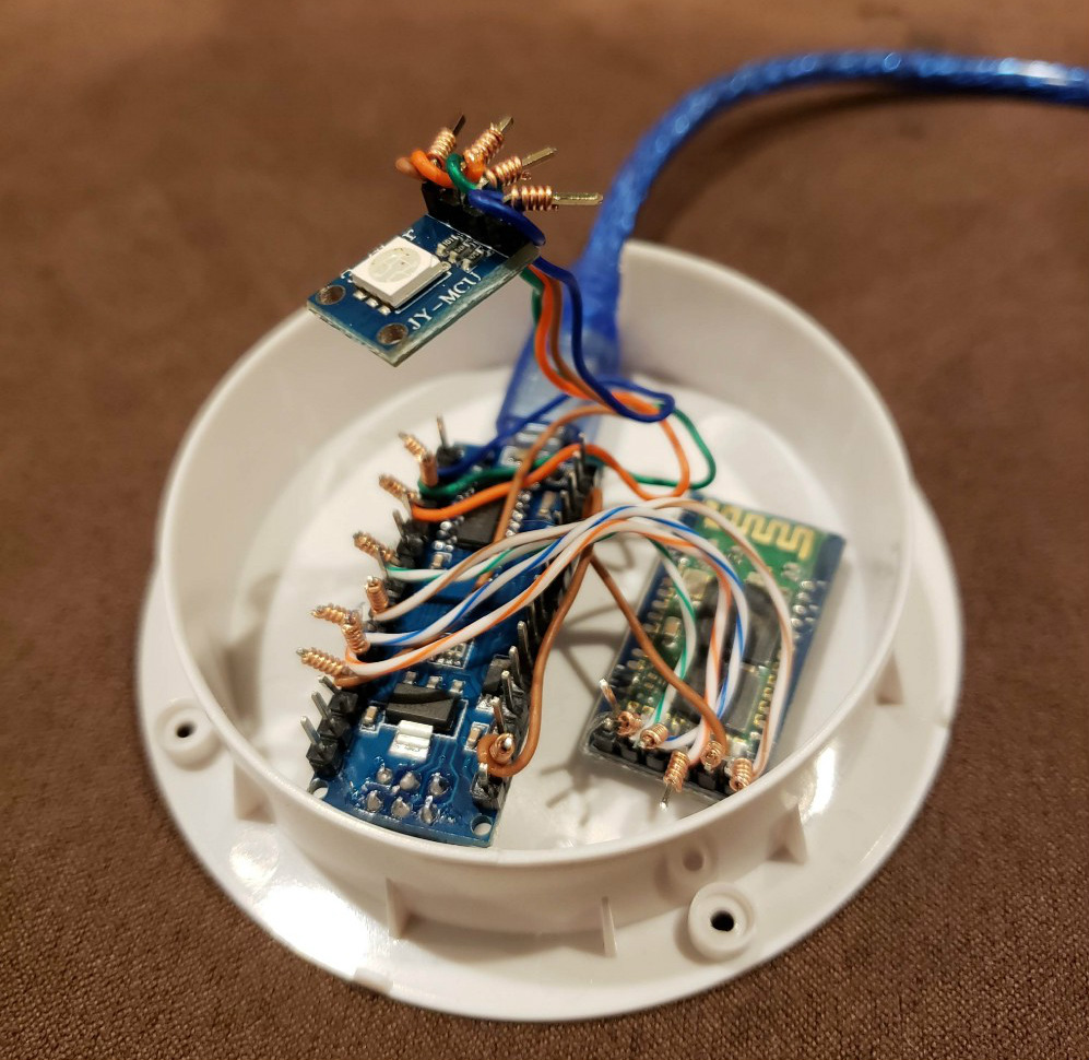
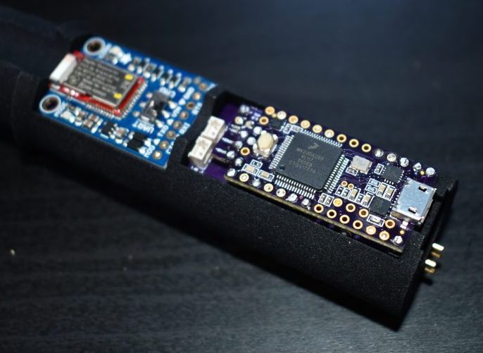
The hilt is filled with an assembly of 18650’s and a Teensy mounted with a custom shield, all fit inside a printed midframe. The whole build is all about robust design that’s easy to assemble. The main board is book-ended by perpendicular PCBs mounted to the ends, one at the top to connect to the blade and one at the bottom to connect to a speaker. Towards the bottom there is space for an optional Bluetooth radio to allow remote RGB control.

Scott is selling this as a product but also provides detailed instructions and parts lists for each component. Assembly instructions for the blade are here. The hilt is here. And pogo adapters are on OSH Park here. An overview of the firmware with links to GitHub is here. Check out a walkthrough of the handle assembly and blade attachment after the break!

Continue reading “Lightsaber Uses Pogo Pins To Make Assembly A Breeze”

This Cup Holder Crystal Ball Tells Your MPG Future

Hybrid vehicles, which combine an eco-friendly electric motor with a gasoline engine for extended range, are becoming more and more common. They’re a transitional technology that delivers most of the advantages of pure electric vehicles, but without the “scary” elements of electric vehicle ownership which are still foreign to consumers such as installing a charger in their home. But one element which hybrids are still lacking is a good method for informing the driver whether they’re running on petroleum or lithium; a way to check at a glance how “green” their driving really is.

[Ben Kolin] and his daughter [Alyssa] have come up with a clever hack that allows retrofitting existing hybrid vehicles with an extremely easy to understand indicator of real-time vehicle efficiency. No confusing graphics or arcade-style bleeps and bloops, just a color-changing orb which lives in the cup holder. An evolved version which takes the form of a smaller “dome light” that sits on the top of the dashboard could be a compelling aftermarket accessory for the hybrid market.

The device, which they are calling the ecOrb, relies on an interesting quirk of hybrid vehicles. The OBD II interface, which is used for diagnostics on modern vehicles, apparently only shows the RPM for the gasoline engine in a hybrid. So if the car is in motion but the OBD port is reporting 0 RPM, the vehicle must be running under electric power.

With a Bluetooth OBD adapter plugged into the car, all [Ben] and [Alyssa] needed was an Arduino Nano clone with a HC-05 module to read the current propulsion mode in real-time. With some fairly simple conditional logic they’re able to control the color of an RGB LED based on what the vehicle is doing: green for driving on electric power, purple for gas power, and red for when the gas engine is at idle (the worst case scenario for a hybrid).

Check out our previous coverage of OBD hacking on the Cadillac ELR hybrid if you’re looking to learn more about what’s possible with this rapidly developing class of vehicle

Continue reading “This Cup Holder Crystal Ball Tells Your MPG Future”

Trashed TV Gets RGB LED Backlight

It might not be obvious unless you’ve taken one apart, but most of the TVs and monitors listed as “LED” are simply LCD panels that use a bank of LEDs to illuminate them from behind. Similarly, what are generally referred to as “LCDs” are LCD panels that use fluorescent tubes for illumination. To get a true LED display with no separate backlight, you need OLED. Confused? Welcome to the world of consumer technology.

With those distinctions in mind, the hack that [Zenodilodon] recently performed on a broken “LED TV” is really rather brilliant. By removing the dead white LED backlights and replacing them with RGB LED strips, he not only got the TV working again, but also imbued it with color changing abilities. Perfect for displaying music visualizations, or kicking your next film night into high gear with a really trippy showing of Seven Samurai.

In the video after the break, [Zenodilodon] starts his RGB transplant by stripping the TV down to its principal parts. The original LEDs were toasted, so they might as well go straight in the bin alongside their driver electronics. But the LCD panel itself was working fine (tested by shining a laser pointer through it to see if there was an image), and the plastic sheets which diffuse the LED backlight were easily salvaged.

With the old LEDs removed, [Zenodilodon] laid out his new strips and soldered them up to the external controller. He was careful to use all white wires, as he was worried colored wires might reflect the white light and be noticeable on the display. After buttoning the TV back up, he went through a few demonstrations to show how the image looked with the white LEDs on, as well as some interesting effects that could be seen when the LEDs are cycling through colors.

The RGB strips don’t light up the display as well as the original backlight did, as there are some obvious dark spots and you can see some horizontal lines where the strips are. But [Zenodilodon] says the effect isn’t too bad in real-life, and considering it was a cheap TV the image quality was probably never that great to begin with.

On the flip side, if you find an LED TV or monitor in the trash with a cracked screen, it might be worth taking it home to salvage its super-bright white LEDs for your lighting projects.

Continue reading “Trashed TV Gets RGB LED Backlight”

Gaze Upon This Daft Punk Helmet’s Rows Of Utterly Perfect Hand-Soldered LEDs

The iconic robot helmets of Daft Punk feature prominently as challenging DIY hardware projects in their own right, and the results never disappoint. But [Nathaniel Stepp]’s photo gallery of his own version really sets the bar in both quality and attention to detail. The helmet uses a Teensy 3.2 as the main processor, and the visor consists of 328 hand soldered through-hole APA106 addressable RGB LEDs. A laser cut panel serves as the frame for the LEDs, and it was heat-formed to curve around the helmet and mate into the surrounding frame. Each LED is meticulously hand-soldered, complete with its own surface mount decoupling cap; there’s no wasted space or excess wire anywhere to be seen. It looks as if a small 3D printed jig was used to align and solder the LEDs one or two columns at a time, which were then transferred to the visor for final connections with the power bus and its neighboring LEDs.

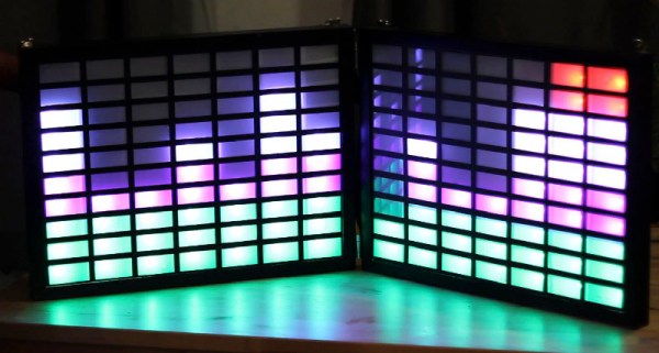
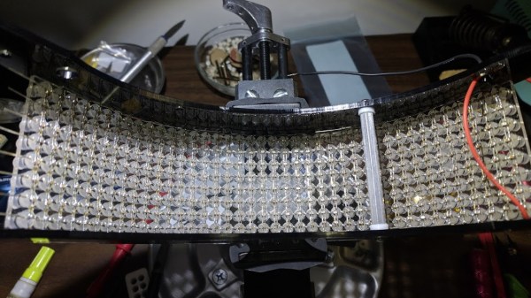
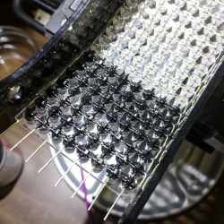
After the whole array was assembled and working, the back of each LED appears to have then been carefully coated in what looks like Plasti-Dip in order to block light, probably to minimize the blinding of the wearer. A small amount of space between each LED allows the eyeballs inside the helmet to see past the light show in the visor.

The perfectly done array of LEDs in the visor is just one of the design elements showing the incredible workmanship and detail in [Nathaniel]’s helmet. His website promises more build details are coming, but in the meantime you can drink in the details shown in the aforementioned photo gallery.

With Halloween approaching, you might be interested in rolling your own Daft Punk inspired helmet. Not ready to do everything from scratch? No problem, because it’s never been easier to make your own with the help of a 3D printer and some LED strips.

[via SparkFun Blog]

When Are Dumb LEDs The Smart Choice?

A couple years ago I got into making electronic conferences badges by building a device for DEFCON 25 shaped like a dragonfly. Like all badges the most important design factor was quite literally how flashy it was, and two years ago I delivered on that with ten RGB LEDs. At the time I planned to hand-assemble each and every of the 105 badges at my kitchen table. Given those constraints, and a desire for electrical and programmatic simplicity, I landed on using APA102s (DotStar’s in Adafruit parlance) in the common 5050 sized package. They were easy to place, easy to design with electrically, simple to control, and friendly to a human pick-n-place machine. Though by the end of the production run I had discovered a few problems, the APA102s were a success.

This year I made a new and improved version of the dragonfly, but applying my lessons learned led me to choose a very different LED architecture than 2017. I swapped out the smart LEDs for dumb ones.

Continue reading “When Are Dumb LEDs The Smart Choice?”

Blink A Pi, Win A Prize

You can plug in a Raspberry Pi, and you can blink a LED. You can visualize data, and now there’s a contest on Hackaday.io to show off your skills. Right now, we’re opening up the Visualize It With Pi contest on Hackaday.io. The challenge? Visualize data with LED strips and panels. Is that ‘data’ actually just a video of Never Gonna Give You Up? We’ll find out soon enough.

The goal of this contest is to combine a Raspberry Pi and its immense processing power and the blinky goodness of LED strips and panels to visualize and interpret data in novel and artistic ways. We’re looking for animation. clarity, and flamboyant flickering. Want some ideas? Check out the World of Light or the American Constitution Candle. We’re looking for the most blinky you can do with a Pi, and yes, there will be prizes.

Prizes

BlinkyTile Explorers Kit

Prizes for the best blinky include, of course, more blinky. The best visualizations from a directly connected sensor, data from an Internet Source, and data from an esoteric data source will each receive some Blinkytape. This is a strip of WS2812b LEDs with an ATMega32u4 embedded on the end. Plug a USB power supply into the Blinkytape, and you get a strip of LEDs in whatever color you want with the ability to push animation frames to the chip on the strip. The Grand Prize winner for this contest will also receive Blinkytile Explorers Kit, a Serpentine LED strip, a LED ring, and two meters of ultra thin LED strip.

Let’s Do This!

The requirements for the contest are simple: just use a Raspberry Pi to drive LED strips or panels, post it as a new project on Hackaday.io, and submit the project to the contest. We’re looking for a full description, source, schematics, and photos and videos of the finished version of the project — do everything you can to show off your work! The contest is open right now, and ends at 08:00 Pacific on October 1st. We know you like to blink those LEDs, so get crackin’.

Buttery Smooth Fades With The Power Of HSV

In firmware-land we usually refer to colors using RGB. This is intuitively pleasing with a little background on color theory and an understanding of how multicolor LEDs work. Most of the colorful LEDs we are use not actually a single diode. They are red, green, and blue diodes shoved together in tight quarters. (Though interestingly very high end LEDs use even more colors than that, but that’s a topic for another article.) When all three light up at once the emitted light munges together into a single color which your brain perceives. Appropriately the schematic symbol for an RGB LED without an onboard controller typically depicts three discrete LEDs all together. So it’s clear why representing an RGB LED in code as three individual values {R, G, B} makes sense. But binding our representation of color in firmware to the physical system we accidentally limit ourselves.

The inside of an RGB LED

Last time we talked about color spaces, we learned about different ways to represent color spatially. The key insight was that these models called color spaces could be used to represent the same colors using different groups of values. And in fact that the grouped values themselves could be used to describe multidimensional spacial coordinates. But that post was missing the punchline. “So what if you can represent colors in a cylinder!” I hear you cry. “Why do I care?” Well, it turns out that using colorspace can make some common firmware tasks easier. Follow on to learn how!

Continue reading “Buttery Smooth Fades With The Power Of HSV”