There are many ways to build your own Macintosh clone, and while the very latest models remain a little inaccessible, there are plenty of Intel-based so-called “Hackintoshes” which deliver an almost up-to-date experience. But the Mac has been around for a very long time now, and its earliest incarnation only has 128k of RAM and a 68000 processor. What can emulate one of those? Along comes [Matt Evans], with a working Mac 128k emulated on a Raspberry Pi Pico. Such is the power of a modern microcontroller that an RP2040 can now be a Mac!
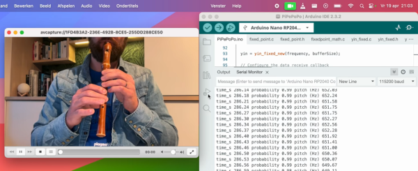
The granddaddy of all Macs might have been a computer to lust after four decades ago, but the reality was that even at the time the demands of a GUI quickly made it under-powered. The RP2040 has plenty of processing power compared to the 68000 and over twice the Mac’s memory, so it seemed as though emulating the one with the other might be possible. This proved to be the case, using the Musashi 68000 interpreter and a self-built emulator which has been spun into a project of its own called umac. With monochrome VGA and USB for keyboard and mouse, there’s MacPaint on a small LCD screen looking a lot like the real thing.
If you want a 1980s Mac for anything without the joy of reviving original hardware, this represents an extremely cheap way to achieve it. If it can be compiled for microcontrollers with more available memory we could see it would even make for a more useful Mac, though your Mac mileage may vary.
Of course, this isn’t the only take on an early Mac we’ve brought you.


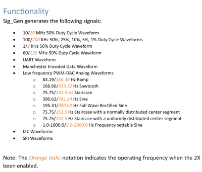 Despite the name it’s not a signal generator as we know it, as it’s not flexible in the signals it generates. Instead, it creates a dozen signals at more or less the same time — from square waves of various frequencies and duty cycles, to a PWM-driven DAC driving eight different waveforms, to Manchester-encoded data I2C/SPI/UART transfers for all your protocol decoder testing.