Tactical Build Makes Machining Splined Shaft A Snap

Quick, what’s 360 divided by 23? It’s easy enough to get the answer, of course, but if you need to machine a feature every 15.652 degrees around a shaft, how exactly would you accomplish that? There are a number of ways, but they all involve some degree of machining wizardry. Or, you can just make the problem go away with a little automation.

The story behind [Tony Goacher]’s Rotary Table Buddy begins with some ATV tracks he got off AliExpress. His idea is to build a specialty electric vehicle for next year’s EMF Camp. The tracks require a splined shaft to drive them, which would need to be custom-made on a milling machine. A rotary table with a dividing plate — not as fancy as this one, of course –is usually the answer, but [Tony] was a little worried about getting everything set up correctly, so he embarked on a tactical automation solution to the problem.

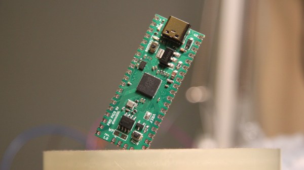
An RP2040 provided the brains of the project, while a NEMA 23 stepper provides the brawn. [Tony] whipped up a quick PCB and 3D printed a case for the microcontroller, a stepper driver, an LCD display, and a few buttons. He 3D printed an adapter and a shaft coupler to mount the stepper motor to a rotary table. From there it was just a matter of coming up with a bit of code to run everything.

There’s a brief video in [Tony]’s blog post that shows Rotary Table Buddy in action, indexing to the next position after cutting one of the 23 splines. He says it took about ten minutes to cut each spline using this setup, which probably makes to total cutting time far less than the amount of time invested in the tool. But that’s hardly the point, and besides, now he’s set up for all kinds of machining operations in the future.

And we sure hope we hear about the EMF Camp build, too.

Low-Cost Display Saved By RP2040

Anyone looking for components for electronics projects, especially robotics, microcontrollers, and IoT devices, has likely heard of Waveshare. They are additionally well-known suppliers of low-cost displays with a wide range of resolutions, sizes, and capabilities, but as [Dmitry Grinberg] found, they’re not all winners. He thought the price on this 2.8-inch display might outweigh its poor design and lack of documentation, and documented his process of bringing it up to a much higher standard with a custom driver for it.

The display is a 320×240 full-color LCD which also has a touchscreen function, but out-of-the-box only provides documentation for sending data to it manually. This makes it slow and, as [Dmitry] puts it, “pure insanity”. His ultimate solution after much poking and prodding was to bit-bang an SPI bus using GPIO on an RP2040 but even this wasn’t as straightforward as it should have been because there are a bunch of other peripherals, like an SD card, which share the bus. Additionally, an interrupt is needed to handle the touchscreen since its default touch system is borderline useless as well, but after everything was neatly stitched together he has a much faster and more versatile driver for this display and is able to fully take advantage of its low price.

For anyone else attracted to the low price of these displays, at least the grunt work is done now if a usable driver is needed to get them up and running. And, if you were curious as to what [Dmitry] is going to use this for, he’s been slowly building up a PalmOS port on hardware he’s assembling himself, and this screen is the perfect size and supports a touch interface. We’ll keep up with that project as it progresses, and for some of [Dmitry]’s other wizardry with esoteric displays make sure to see what he’s done with some inexpensive e-ink displays as well.

PicoCray - Raspberry Pi Pico Cluster

Parallel Computing On The PicoCray RP2040 Cluster

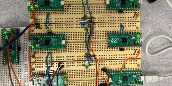
[ExtremeElectronics] cleverly demonstrates that if one Raspberry Pi Pico is good, then nine must be awesome.  The PicoCray project connects multiple Raspberry Pi Pico microcontroller modules into a parallel architecture leveraging an I2C bus to communicate between nodes.

The same PicoCray code runs on all nodes, but a grounded pin on one of the Pico modules indicates that it is to operate as the controller node.  All of the remaining nodes operate as processor nodes.  Each processor node implements a random back-off technique to request an address from the controller on the shared bus. After waiting a random amount of time, a processor will check if the bus is being used.  If the bus is in use, the processor will go back to waiting.  If the bus is not in use, the processor can request an address from the controller.

Once a processor node has an address, it can be sent tasks from the controller node.  In the example application, these tasks involve computing elements of the Mandelbrot Set. The particular elements to be computed in a given task are allocated by the controller node which then later collects the results from each processor node and aggregates the results for display.

The name for this project is inspired by Seymore Cray. Our Father of the Supercomputer biography tells his story including why the Cray-1 Supercomputer was referred to as “the world’s most expensive loveseat.” For even more Cray-1 inspiration, check out this Raspberry Pi Zero Cluster.

One of the PCB projects involved being held in the author's hands - a large-ish green board, with two Pi Picos visible on it

RP2040 And 5V Logic – Best Friends? This FX9000P Confirms!

Over the years, we’ve seen some modern microcontrollers turn out to be 5V-tolerant – now, RP2040 joins the crowd. Half a year ago, when we covered an ISA card based on a Pi Pico, [Eben Upton] left a comment saying that RP2040 is, technically, 5V tolerant for GPIO input purposes. The datasheets don’t state this because the reality of 5V tolerance isn’t the same as for natively 5V-tolerant chips – for instance, it doesn’t extend all the way to 5.5V for it to be ‘legally’ 5V-tolerant, as in, what 5V tolerance typically means when mentioned in a datasheet.

Having read that comment, [Andrew Menadue] has set out to test-drive the RP2040 GPIO capabilities, in a perfectly suited real-world scenario. He’s working with retro tech like Z80-era computers, using RP2040 boards for substituting entire RAM and ROM chips that have died in his FX9000P. Not only do the RP2040-driven replacements work wonders, using RP2040 boards also turns out to be way cheaper than sourcing replacements for chips long out of production!

Previously, [Andrew] used level shifter chips for interfacing the RP2040 with 5V systems, but he’s rebuilt a few designs of his without level shifters for the sake of this experiment. Now, he reports that, so far, those boards have been running long-term without problems. Together with [Eben]’s comment, this instills confidence in us when it comes to our RP2040 forays and 5V inputs.

There are a number of important caveats to this, that you should read up on. Some major points – certain GPIOs (like ADC ones) can’t take it, the GPIOs aren’t 5V-tolerant when set to output, and you shouldn’t feed the GPIOs 5V when the RP2040’s VDDIO is not powered up. [Andrew] points out one such case himself – one board of his has shed all level shifters except for the 8-bit address bus, which is driven by either the CPU or the RP2040 at different times, and that would result in 5V on an output-set GPIO when contention happens. All in all, if you’re working with 5V logic and your application is more hacking than business-critical stuff, you can shed the level shifters, too.

Continue reading “RP2040 And 5V Logic – Best Friends? This FX9000P Confirms!”

Could 1080p Video Output From The RP2040 Be Possible?

Modern microcontrollers often have specs comparable with or exceeding early gaming consoles. However, where they tend to fall short is in the video department, due to their lack of dedicated graphics hardware. With some nifty coding, though, great things can be achieved  — as demonstrated by [TEC_IST]’s project that gets the RP2040 outputting 1080p video over HDMI.

The project builds on earlier work that saw the RP2040 outputting digital video over DVI. [TEC_IST] realized that earlier methods already used up 30% of the chip’s processing power just to reach 320×240 output. To get to 1080p resolution would require a different tack. The idea involved using the 32-bit architecture of the RP2040 to output a greater data rate to suit the higher resolution. The RP2040 can do a 32-bit move instruction in a single clock cycle, which, with 30 GPIO pins, would be capable of a data rate of 3.99 Gbits/second at the normal 133 MHz clock speed. That’s more than enough for 1080p at 60 Hz with a 24-bit color depth.

Due to the limitations of the chip, though, some extra hardware would be required. [TEC_IST] has drawn up a design that uses external RAM as a framebuffer, while using shift registers and other supporting logic to handle dumping out signals over HDMI. This would just leave the RP2040 to handle drawing new content, without having to redraw existing content every frame.

[TEC_IST] has shared the design for a potential 1080p HDMI output board for the RP2040 on GitHub and is inviting comment from the broader community. They’re yet to be built and tested, so it’s all theoretical at this stage. Obviously, a lot of heavy lifting is being done off-board the microcontroller here, but it’s still fun to think of such a humble chip doing such heavy-duty video output. Continue reading “Could 1080p Video Output From The RP2040 Be Possible?”

Compose Any Song With Twelve Buttons

Limitations placed on any creative process often paradoxically create an environment in which creativity flourishes. A simple overview of modern pop, rock, or country music illustrates this principle quite readily. A bulk of these songs are built around a very small subset of music theory, often varying no more than the key or the lyrics. Somehow, almost all modern popular music exists within this tiny realm. [DeckerEgo] may have had this idea in mind when he created this tiny MIDI device which allows the creation of complex musical scores using a keyboard with only 12 buttons.

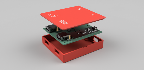
The instrument is based around the Adafruit MacroPad, which is itself built on the RP2040 chip. As a MIDI device, it needs to be connected to a computer running software which can support MIDI instruments, but once its assembled and given its firmware, it’s ready to rock. A musician can select one of any number of musical scales to operate within, and the 12 keys on the pad are mapped to the 12 chromatic notes within that scale. It can also be used to generate drum tracks or other backing tracks to loop before being used to create melodies as well.

[DeckerEgo] took a bit of inspiration from an even simpler macro pad we featured before which is based around the idea that a shockingly high number of songs use the same four chords. His macro pad includes creation of chord progressions as well, but expands on that idea to make more complete compositions possible. And, for those looking to build their own or expand on this project, he has also made all of the source code available on his GitHub page.

Continue reading “Compose Any Song With Twelve Buttons”

Working Artificial Horizon Built Into A Single LEGO Brick

Back in the day, LEGO spaceship sets used to come with these little wedge blocks painted with fake gauges on them. [James “Ancient” Brown] decided that wasn’t good enough. Thus, he took everything he needed for a functional artificial horizon, and stuffed it inside a single LEGO brick. Yes, it’s real, and it’s spectacular.

We featured [James’] electronics-infused bricks some time ago when they first hit the Internet. The basic story is that he managed to cram an OLED screen and an RP2040 into a silicone mold for a LEGO-compatible brick. His first iterations stunned the world, as they ran pretty monochrome animations that brought life to formerly-inanimate chunk of plastic.

Since then, [James] has been busy. He’s managed to squeeze an accelerometer into the brick form factor as well. That allowed him to build a LEGO piece which displays an impressively-smooth artificial horizon display, as you might find in an aircraft. He demonstrates this by putting the instrument on a LEGO craft and zooming it around the room. All the while, the artificial horizon accurately tracks the motions of the craft.

It’s an impressive build, and something we’d love to see included in future LEGO vehicles…even if they’re just 3D renders. Continue reading “Working Artificial Horizon Built Into A Single LEGO Brick”