OpenEMS Makes Electromagnetic Field Solving… Merely Difficult

To ordinary people electronics is electronics. However, we know that the guy you want wiring your industrial furnace isn’t the guy you want designing a CPU. Neither of those guys are likely to be the ones you want building an instrumentation amplifier. However, one of the darkest arts of the electronic sects is dealing with electromagnetic fields. Not only is it a rare specialty, but it requires a lot of high-powered math. Enter OpenEMS, a free and open electromagnetic field solver.

We would like to tell you that OpenEMS makes doing things like antenna analysis easy. But that’s like saying Microsoft Word makes it easy to write a novel. In one sense, yes, but you still need to know what you are doing. In fairness, though, the project does provide a good set of tutorials, ranging from a simple wave guide to a sophisticated phased array of patch antennas. Our advice? Start with the waveguide and work your way up from there.

The software uses Octave or MATLAB for scripting, plotting, and support. You can download it for Windows or Linux.

If you want to start with something more intuitive for electromagnetic field visualization, this might help. If you prefer your models more concrete and less abstract, perhaps you should work at Lincoln Lab.

Simulating The Learn-by-Fixing CPU

Last time I looked at a simple 16-bit RISC processor aimed at students. It needed a little help on documentation and had a missing file, but I managed to get it to simulate using a free online tool called EDA Playground. This time, I’ll take you through the code details and how to run the simulation.

You’ll want to refer to the previous post if you didn’t read it already. The diagrams and tables give a high-level overview that will help you understand the files discussed in this post.

If you wanted to actually program this on a real FPGA, you’d have a little work to do. The memory and register initialization is done in a way that works fine for simulation, but wouldn’t work on a real FPGA. Anyway, let’s get started!

Continue reading “Simulating The Learn-by-Fixing CPU”

Desktop Factory Teaches PLC Programming

How to train young engineers in industrial automation is a thorny issue. Most factories have big things that can do a lot of damage and cost tons of money if the newbie causes a crash. Solution: shrink the factory down to desktop size and let them practice on that.

Luckily for [Vadim], there’s an off-the-shelf solution for miniaturizing factory automation: FischerTechnik industrial training models. The models have motors, conveyors, pneumatic cylinders, and sensors galore, but the controller is not exactly the industry standard programmable logic controller (PLC). [Vadim] set out to remedy this by building an interface between the FischerTechnik models and a Siemens PLC. He went through a couple of revisions of his board, including one using rivets from the sewing store to interface with the FischerTechnic connectors. Eventually, he settled on more robust connectors and came up with a board that lets students delve into PLC programming without killing anyone. The video below shows it going through its paces; we can only imagine where playing with these kits as a kid would have led us.

As great as [Vadim]’s system is for training engineers, we can also see it helpful in getting kids interested in a career in industrial automation. We recently covered a similar effort to show kids big science using LEGO Mindstorms. Both of these can help get STEM kids to see the wider world of technical careers and perhaps steer them into automation. After all, the people who make the robots are probably going to be the last ones obsoleted, right?

Continue reading “Desktop Factory Teaches PLC Programming”

Learn Neural Network And Evolution Theory Fast

[carykh] has a really interesting video series which can give a beginner or a pro a great insight into how neural networks operate and at the same time how evolution works. You may remember his work creating a Bach audio producing neural network, and this series again shows his talent at explaining the complex topic so anyone may understand.

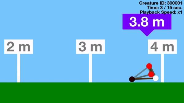
He starts with 1000 “creatures”. Each has an internal clock which acts a bit like a heart beat however does not change speed throughout the creature’s life. Creatures also have nodes which cause friction with the ground but don’t collide with each other. Connecting the nodes are muscles which can stretch or contract and have different strengths.

At the beginning of the simulation the creatures are randomly generated along with their random traits. Some have longer/shorter muscles, while node and muscle positions are also randomly selected. Once this is set up they have one job: move from left to right as far as possible in 15 seconds.

Each creature has a chance to perform and 500 are then selected to evolve based on how far they managed to travel to the right of the starting position. The better the creature performs the higher the probability it will survive, although some of the high performing creatures randomly die and some lower performers randomly survive. The 500 surviving creatures reproduce asexually creating another 500 to replace the population that were killed off.

The simulation is run again and again until one or two types of species start to dominate. When this happens evolution slows down as the gene pool begins to get very similar. Occasionally a breakthrough will occur either creating a new species or improving the current best species leading to a bit of a competition for the top spot.

We think the series of four short YouTube videos (all around 5 mins each) that kick off the series demonstrate neural networks in a very visual way and make it really easy to understand. Whether you don’t know much about neural networks or you do and want to see something really cool, these are worthy of your time.

Continue reading “Learn Neural Network And Evolution Theory Fast”

LTSpice For Radio Amateurs (and Others)

We don’t think [VK4FFAB] did himself a favor by calling his seven-part LTSpice tutorial LTSpice for Radio Amateurs. Sure, the posts do focus on radio frequency analysis, but these days lots of people are involved in radio work that aren’t necessarily hams.

Either way, if you are interested in simulating RF amplifiers and filters, you ought to check these posts out. Of course, the first few cover simple things like voltage dividers just to get your feet wet. The final part even covers a double-balanced mixer with some transformers, so there’s quite a range of material.

Continue reading “LTSpice For Radio Amateurs (and Others)”

Building A Replica Of An Ultraluxury Watch

In the world of late-stage capitalism, unchecked redistribution of wealth to the upper classes has led to the development of so-called ultraluxury watches. Free from any reasonable constraints on material or R&D cost, manufacturers are free to explore the outer limits of the horological art. [Karel] is an aspiring engineer and watch enthusiast, and has a taste for the creations of Urwerk. They decided to see if they could create a replica of the UR202 watch with nothing more than the marketing materials as a guide.

[Karel]’s first job was to create a model of the watch in CAD. For a regular watch this might be simple enough, but the UR202 is no run-of-the-mill timepiece. It features a highly irregular mechanism, full of things like a turbine regulated winding mechanism, telescoping rods instead of minute hands, and tumbling rotors to indicate the hours. The official product sheet bears some of these features out. Through careful analysis of photos and watching videos frame-by-frame, they managed to recreate what they believe to be a functioning mechanical model within their CAD software.

It was then time to try and build the timepiece for real. It was then that [Karel] started hitting some serious stumbling blocks. As a humble engineering student, it’s not often possible to purchase an entire machine shop capable of turning out the tiny, precision parts necessary to make even a basic watch mechanism. Your basic 3D printer squirting hot plastic isn’t going to cut it here. Farming out machining wasn’t an option as the cost would be astronomical. [Karel] instead decided on combining a Miyota movement with a machined aluminum base plate and parts 3D printed using a process known as “Multijet Modelling” which essentially is an inkjet printhead spitting out UV curable polymer.

In the end, [Karel] was able to get just the tumbling hour indicator working. The telescoping minute hand, compressed air turbine winding system, and other features didn’t make it into the build. However, the process of simulating these features within a CAD package, as well as manufacturing a semi-functional replica of the watch, was clearly a powerful learning experience. [Karel] used their passion to pursue a project that ended up giving them a strong grasp of some valuable skills, and that is something that is incredibly rewarding.

We’ve seen others trying to fabricate parts of a wristwatch at home. Keep your horological tips coming in!

[Thanks to Str Alorman for the tip!]

ENIAC: The Way We Were

When I first got interested in computers, it was all but impossible for an individual to own a computer outright. Even a “small” machine cost a fortune not to mention requiring specialized power, cooling, and maintenance. Then there started to be some rumblings of home computers (like the Mark 8 we recently saw a replica of) and the Altair 8800 burst on the scene. By today’s standards, these are hardly computers. Even an 8-bit Arduino can outperform these old machines.

As much disparity as there is between an Altair 8800 and a modern personal computer, looking even further back is fascinating. The differences between the original computers from the 1940s and anything even remotely “modern” like an Altair or a PC are astounding. If you are interested in that kind of history, you should read a paper entitled “Electronic Computing Circuits of the ENIAC” by [Arthur W. Burks].

These mid-century designers used tubes and were blazing new ground. Part of what makes the ENIAC so different is that it had a different design principle than a modern computer. It was less a general purpose stored-program computer and more of a collection of logic circuits that could be configured to solve problems — sort of a giant vacuum tube FPGA, if you will. It used some internal representations that proved to be suboptimal which also makes it seem strange. The EDSAC — a later device — was closer to what we think of as a computer. Yet the ENIAC was a major step in the direction of a practical digital computer.

Cost and Size

eniac
Programming the ENIAC in 1951 (±4 years)
[Image Source: Public Domain]
The size of ENIAC is hard to imagine. The device had about 18,000 tubes, 7,000 diodes, 70,000 resistors, 10,000 capacitors, and 6,000 switches. There were 5 million hand-soldered joints! ([Thomas Haigh] tells us that while this is widely reported, the real number was about 500,000.) Physically, it stood 10 feet tall, 3 feet deep, and 100 feet long. The tube filaments alone required 80 kW of power. Even the cooling system consumed 20 kW. In total, it took 150 kW to run the beast.

The cost of the machine was about $487,000. Almost a half-million dollars in 1946 is plenty. But that’s nearly seven million dollars in today’s money. What was worth that kind of expenditure? The military built firing tables for shell trajectories. From the [Burks] paper:

“A skilled computer with a desk machine can compute a 60-second trajectory in about twenty hours…”

Keep in mind that in 1946, a computer was a person. [Burks] goes on to say that a differential analyzer can do the same job in 15 minutes. ENIAC, on the other hand, could do it in 30 seconds and with a greater precision than the differential analyzer.

Continue reading “ENIAC: The Way We Were”