Virtual Nodes, Real Waves: A Colpitts Walkthrough

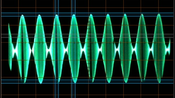
If you’ve ever fumbled through circuit simulation and ended up with a flatline instead of a sine wave, this video from [saisri] might just be the fix. In this walkthrough she demonstrates simulating a Colpitts oscillator using NI Multisim 14.3 – a deceptively simple analog circuit known for generating stable sine waves. Her video not only shows how to place and wire components, but it demonstrates why precision matters, even in virtual space.

You’ll notice the emphasis on wiring accuracy at multi-node junctions, something many tutorials skim over. [saisri] points out that a single misconnected node in Multisim can cause the circuit to output zilch. She guides viewers step-by-step, starting with component selection via the “Place > Components” dialog, through to running the simulation and interpreting the sine wave output on Channel A. The manual included at the end of the video is a neat bonus, bundling theory, waveform visuals, and circuit diagrams into one handy PDF.

If you’re into precision hacking, retro analogue joy, or just love watching a sine wave bloom onscreen, this is worth your time. You can watch the original video here.

Continue reading “Virtual Nodes, Real Waves: A Colpitts Walkthrough”

Recreating The Analog Beauty Of A Vintage Tektronix Oscillator

Tektronix must have been quite a place to work back in the 1980s. The company offered a bewildering selection of test equipment, and while the digital age was creeping in, much of their gear was still firmly rooted in the analog world. And some of the engineering tricks the Tek wizards pulled off are still the stuff of legend.

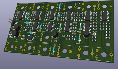
One such gem of analog design was the SG505, an ultra-low-distortion oscillator module that [Paul] is trying to replicate with modern parts. That’s a tall order since not only did the original specs on this oscillator call for less than 0.0008% total harmonic distortion over a frequency range of 20 Hz to 20 kHz, but a lot of the components it used are no longer manufactured. Tek also tended to use a lot of custom parts, especially mechanical ones like the barrel switch used to select attenuation levels in the SG505, leaving [Paul] no choice but to engineer his way around them.

So far, [Paul] has managed to track down most of the critical components or source suitable substitutes. One major win was locating the original J-FET Tek used in the oscillator’s AGC circuit. One part that’s proven more elusive is the potentiometer that Tek used to adjust the frequency; who knew that finding a dual-gang precision wirewound 10k single-turn pot with no physical stop would be such a chore?

[Paul] still seems to be very much in the planning stages of this project yet, and that’s probably for the best since projects such as these live and die on proper planning. We’re keen to see how this develops, and we’re very much looking forward to seeing the FFT results. We also imagine he’ll be busting out his custom curve tracer at some point in the build, too.
This Frequency Generator Knows How To Get Down

What kind of clever things could you do with a signal that had a period of 2 hours? Or 20? Any ideas? No seriously, tell us. Because [Joseph Eoff] has come up with a way to produce incredibly low frequency signals that stretch out for hours, and we’d love to figure out what we can do with it.

To be fair, it’s not like [Joseph] has any ideas either. He thought it would be an interesting project, and figures now that he has the technology, maybe some application will come to him. They say that if you’ve got a hammer everything looks like a nail, so maybe the next project he sends our way will be a sinusoidal fish feeder.

[Joseph] says doing the software side of things with Pure Data wasn’t a problem, but getting it out of the computer proved to be tricky. It turns out that your average computer sound card isn’t equipped to handle frequencies down into the millihertz range (big surprise), so they need to be coaxed out with some extra hardware. Using a simple circuit not unlike an AM demodulator, he’s able to extract the low-frequency signal from a 16 kHz carrier.

So if you ever find yourself in need of a handful of hertz, now you’ve got the tool to generate them. At least it’s more practical than how they used to generate low frequency signals back in the 1900s.

Root Mean Square

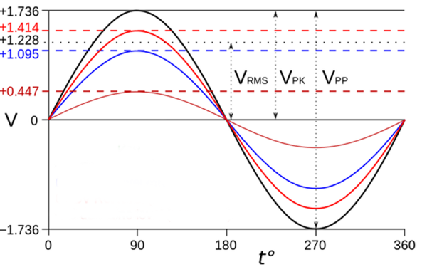
The first time I was in school for electrical engineering (long story), I had a professor who had never worked in the industry. I was in her class and the topic of the day was measuring AC waveforms. We got to see some sine waves centered on zero volts and were taught that the peak voltage was the magnitude of the voltage above zero. The peak to peak was the voltage from–surprise–the top peak to the bottom peak, which was double the peak voltage. Then there was root-mean-square (RMS) voltage. For those nice sine waves, you took the peak voltage and divided by the square root of two, 1.414 or so.

You know that kid in the front of the class? They were in your class, too. Always raising their hand with some question. That kid raised his hand and asked the simple question: why do we care about RMS voltage? I was stunned when I heard the professor answer, “I think it is because it is so easy to divide by the square root of two.”

Continue reading “Root Mean Square”

Scope Noob: Microcontroller Quirks With DDS

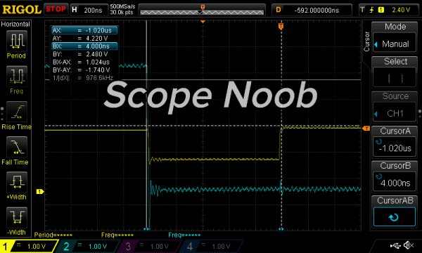
In this installment of Scope Noob I’m working with Direct Digital Synthesis using a microcontroller. I was pleasantly surprised by some of the quirks which I discovered during this process. Most notably, I had a chance to look at errant triggers solved by using holdoff and a few timing peculiarities introduced by my use of the microcontroller. Here’s a video synopsis but I’ll cover everything in-depth after the break.

Continue reading “Scope Noob: Microcontroller Quirks With DDS”

Direct Digital Synthesis (DDS)

Direct Digital Synthesis (DDS) Explained By [Bil Herd]

One of the acronyms you may hear thrown around is DDS which stands for Direct Digital Synthesis. DDS can be as simple as taking a digital value — a collection of ones and zeroes — and processing it through a Digital to Analog Converter (DAC) circuit. For example, if the digital source is the output of a counter that counts up to a maximum value and resets then the output of the DAC would be a ramp (analog signal) that increases in voltage until it resets back to its starting voltage.

This concept can be very useful for creating signals for use in a project or as a poor-man’s version of a signal or function generator. With this in mind I set out here to demonstrate some basic waveforms using programmable logic for flexibility, and a small collection of resistors to act as a cheap DAC. In the end I will also demonstrate an off-the-shelf and inexpensive DDS chip that can be used with any of the popular micro-controller boards available that support SPI serial communication.

All of the topics covered in the video are also discussed further after the break.

Continue reading “Direct Digital Synthesis (DDS) Explained By [Bil Herd]”

Function Generator With Zero CPU Cycles

No one is sitting around their workbench trying to come up with the next great oscilloscope or multimeter, but function generators still remain one of the pieces of test equipment anyone – even someone with an Arduino starter pack – can build at home. Most of these function generators aren’t very good; you’re lucky if you can get a sine wave above the audio spectrum. [Bruce Land] had the idea to play around with DMA channels on a PIC32 and ended up with a function generator that uses zero CPU cycles. It’s perfect for a homebrew function generator build, or even a very cool audio synthesizer.

The main obstacles to generating a good sine wave at high frequencies are a high sample rate and an accurate DAC. For homebrew function generators, it’s usually the sample rate that’s terrible; it’s hard pushing bits out a port that fast. By using the DMA channel on a PIC32, [Bruce] can shove arbitrary waveforms out of the chip without using any CPU cycles. By writing a sine wave, or any other wave for that matter, to memory, the PIC32 will just spit them out and leave the CPU to do more important work.

[Bruce] was able to generate a great-looking sine wave up to 200 kHz, and the highest amplitude of the harmonics was about 40db below the fundamental up to 100 kHz. That’s a spectacular sine wave, and the perfect basis for a DIY function generator build.